627 Series
11
BLOCKED THROAT
BACK-UP RINGS (KEY 45)
BLOCKED THROAT
(KEY 43)
BLOCKED THROAT
O-RINGS (KEY 44)
W4791
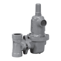
TYPES 627M, 627HM, AND 627MR
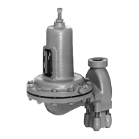
Figure 5. Stem Assemblies
The disk assembly and orice can be inspected,
removed, and replaced without removing the regulator
body from the line connections. Refer to the Body
Area Maintenance Procedures.
Body Area Maintenance Procedures
These procedures are for gaining access to the disk
assembly, orice, diaphragm casing O-ring, and stem
assembly. All pressure must be released from the
diaphragm casing before performing these steps.
While using the following procedures, refer to
Figures 7 through 13 for key number locations.
Replacing the Disk Assembly or Orice
1. To inspect and replace the disk assembly (key 9)
or orice (key 2), remove the cap screws (key 3,
Figure 5), and separate the diaphragm casing
(key 5) from the body (key 1).
2. Inspect and, if necessary, remove the orifice
(key 2). If removed, coat the threads of the
replacement orifice with lubricant and torque to
25 foot-pounds / 34 N•m.
3. Inspect the disk assembly (key 9) and, if necessary,
remove the hair pin clip (key 13) that holds the disk
assembly (key 9) in place. If replacing the disk
assembly is the only maintenance required, skip to
step 16.
Replacing the Stem Assembly
If it is necessary to perform maintenance on the stem
assembly, continue with steps 4 through 8 and 15
through 19 for Types 627, 627H, 627R, and 627LR
regulators, or steps 9 through 19 for Types 627M,
627HM, and 627MR regulators.
Perform steps 4 through 8 for Types 627, 627H,
627R, and 627LR Regulators only:
4. Use steps 5 through 8 to remove and replace the
stem assembly.
5. Remove the boost body (key 6), stabilizer (key 7),
and stem guide (key 8) from the diaphragm casing
(key 5). Unhook and remove the stem (key 10)
from the diaphragm casing (key 5).
6. Remove and inspect the diaphragm casing
O-ring (key 4, Figure 7, 8, 9, or 12) and replace
it if necessary.
W4792
TYPES 627, 627H, 627R, AND 627LR
PITOT TUBE
AND TAB FOR
TYPE 627 ONLY
ORIFICE
(KEY 2)
BODY
(KEY 1)
CAP
SCREW
(KEY 3)
LEVER
(KEY 15)
DIAPHRAGM
CASING (KEY 5)
STEM BACK-UP
RINGS
(KEY 12)
STEM O-RING
(KEY 11)
STEM (KEY 10)
STEM GUIDE
(KEY 8)
STABILIZER
(KEY 7)
DIAPHRAGM CASING
O-RING (KEY 4)
BOOST BODY
(KEY 6)
DISK
ASSEMBLY
(KEY 9)
HAIR PIN CLIP
(KEY 13)
 Loading...