627 Series
5
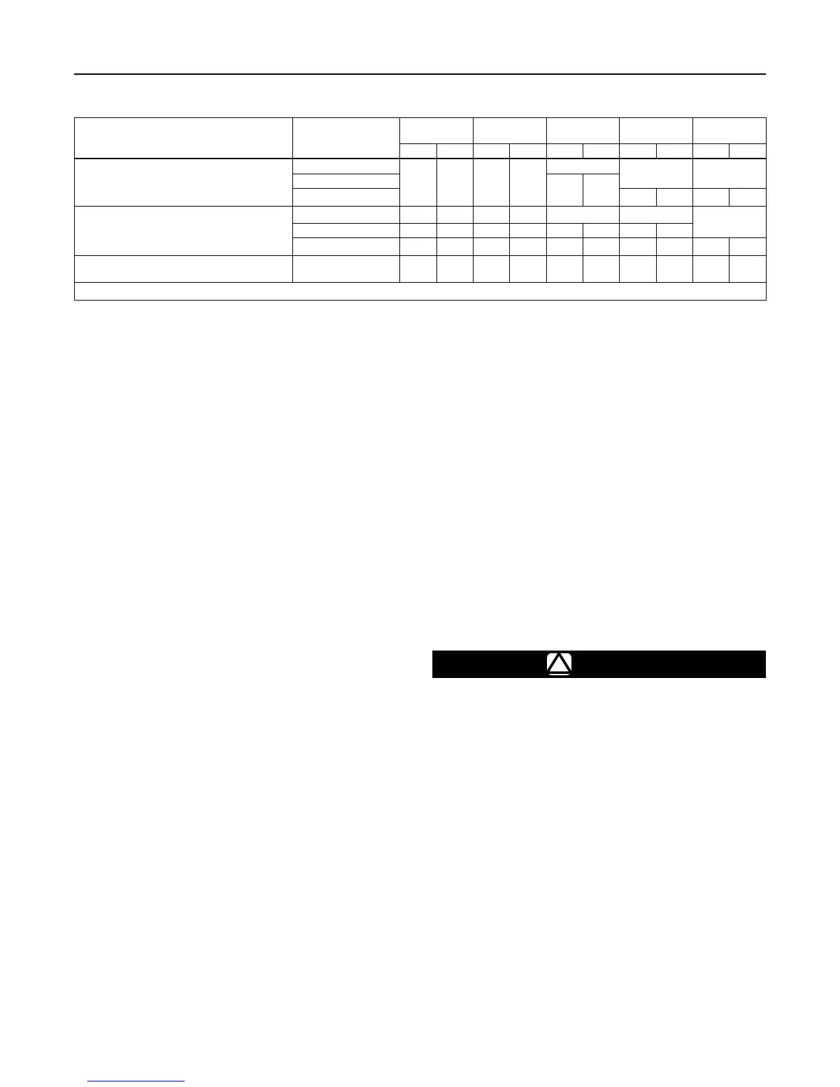
Table 2. Maximum Spring and Diaphragm Casing Pressure
(1)
MAXIMUM PRESSURE DESCRIPTION
DIAPHRAGM
CASING MATERIAL
TYPE 627
TYPES 627R
AND 627LR
TYPE 627M TYPE 627MR
TYPES 627H
AND 627HM
psig bar psig bar psig bar psig bar psig bar
Maximum pressure to spring and diaphragm
casings to prevent leak to atmosphere other than
relief action (internal parts damage may occur)
Die cast aluminum
250 17.2 250 17.2
Not Available
Not Available Not Available
Ductile iron
250 17.2
Steel or Stainless steel 250 17.2 800 55.2
Maximum pressure to spring and diaphragm
casings to prevent burst of casings during
abnormal operation (leak to atmosphere and
internal parts damage may occur)
Die cast aluminum 375 25.9 375 25.9 Not Available Not Available
Not Available
Ductile iron 465 32.1 465 32.1 465 32.1 465 32.1
Steel or Stainless steel 1500 103 1500 103 1500 103 1500 103 1500 103
Maximum diaphragm casing overpressure (above
setpoint) to prevent damage to internal parts
All materials 60 4.1 120 8.3 60 4.1 120 8.3 120 8.3
1. If the spring case is pressurized, a metal adjusting screw cap is required. Contact your local Sales Ofce for details.
(for example, disk broken off or disk erosion), the
pusher post contacts the lever retainer causing the
relief valve assembly to open. Since the diaphragm
continues to rise as downstream pressure builds, it
opens the relief valve; thereby, opening the valve.
This internal relief may be adequate for the application.
Downstream Control Line for Type 627M, 627HM,
or 627MR Regulator—A Type 627M, 627HM, or
627MR regulator has a blocking throat stem seal
with O-rings and a 1/4 NPT control line connection in
the diaphragm case. A regulator with a downstream
control line is used for monitoring applications or
other applications where other equipment is installed
between the regulator and the pressure control point.
The stem seal separates the body outlet pressure
from the diaphragm case.
Installation
Regulator operation within ratings does not preclude
the possibility of damage from debris in the lines
or from external sources. A regulator should be
inspected for damage periodically and after any
overpressure condition. Key numbers referenced
in this section are shown in Figures 7 through 13.
Ensure that the operating temperature capabilities
listed in Specications section are not exceeded.
Note
If the regulator is shipped mounted on
another unit, install that unit according
to the appropriate Instruction Manual.
Perform steps 1 through 6 for all types of regulators:
1. Only personnel qualied through training and
experience should install, operate, or maintain
this regulator.
2. For a regulator that is shipped separately, make
sure that there is no damage to or foreign material
in the regulator.
3. Ensure that all tubing and piping have been blown
free of foreign debris.
4. The regulator may be installed in any position as
long as the ow through the body is in the direction
indicated by the arrow cast on the body.
5. If continuous operation is required during
inspection or maintenance, install a three-valve
bypass around the regulator.
!
WARNING
A regulator may vent some gas to the
atmosphere. In hazardous or ammable
gas service, vented gas may accumulate
and cause personal injury, death, or
property damage due to re or explosion.
Vent a regulator in hazardous gas service
to a remote, safe location away from air
intakes or any hazardous area. The vent
line or stack opening must be protected
against condensation or clogging.
6. Position the body (key 1) and/or diaphragm spring
case (key 29) so it will not collect moisture or
debris into the screened vent. If the regulator
requires repositioning, refer to the Body Area
Maintenance Procedures and/or the Diaphragm
and Spring Case Area Maintenance Procedures
in the Maintenance section to reposition the
screened vent for the application.
 Loading...