Table 3. Maximum Inlet Pressures and Temperatures
Parts List
Type 92B Main Valve
Key Description
19 Drive Screw
20 Warning Label (Cast iron only) (not shown)
21 Nameplate
51 Valve Body Assembly
52 Bottom Flange Assembly
53 Guide Bushing
54* Gasket
55 Cap Screw, For Cast iron and Steel bodies
56 Valve Plug
BODY
MATERIAL
END CONNECTION
MAXIMUM INLET PRESSURE MAXIMUM TEMPERATURE
bar psig °C °F
Cast Iron
NPT 17.2 250 208 406
CL125 FF 8.6 125 178 353
CL250 FF 17.2 250 208 406
Steel
NPT, SWE 20.7 300 232 450
CL150 RF 12.8 185 232 450
CL300 RF 20.7 300 316
(1)
600
(1)
PN 16/25/40 (DN 25, 40, 50 and 80 /
NPS 1, 1-1/2, 2 and 3)
20.7 300 316
(1)
600
(1)
PN 16 (DN 100 / NPS 4) 12.8 185 232 450
PN 25/40 (DN 100 / NPS 4) 20.7 300 316
(1)
600
(1)
Stainless Steel
NPT 20.7 300 232 450
CL150 RF 12.1 175 232 450
CL300 RF 20.7 300 316
(1)
600
(1)
PN 16/25/40 (DN 25, 40, 50 and 80 /
NPS 1, 1-1/2, 2 and 3)
20.7 300 316
(1)
600
(1)
PN 16 (DN 80 and 100 / NPS 3 and 4) 12.1 175 232 450
PN 25/40 (DN 80 and 100 / NPS 3 and 4) 20.7 300 316
(1)
600
(1)
1. 232°C / 450°F with standard seat ring, 316°C / 600°F with seal weld option.
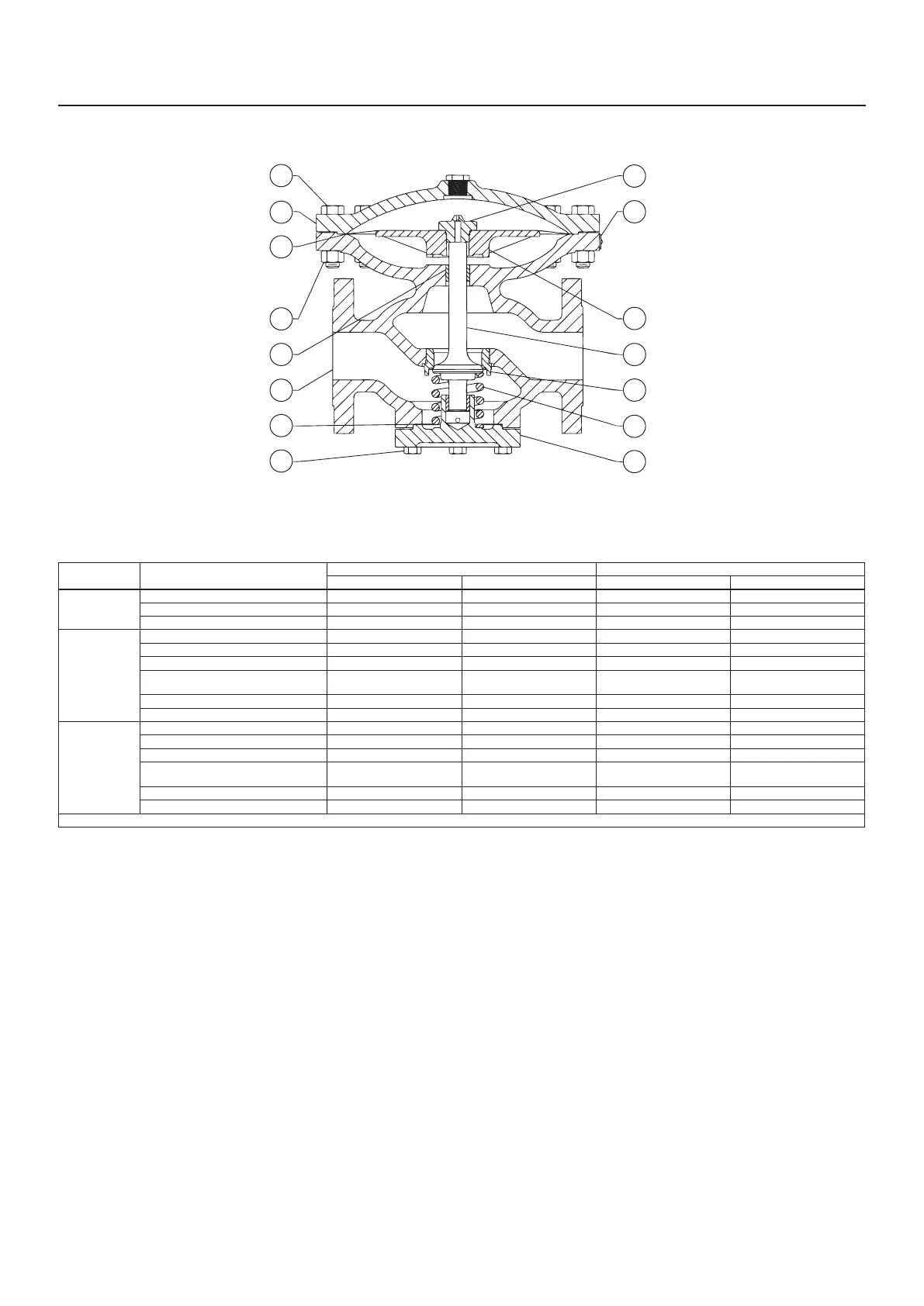
30A6348-B1A
Figure 1. Type 92B Main Valve Assembly
*Recommended spare part.
Key Description
57 Spring
58* Seat Ring
59 Diaphragm Head
60* Diaphragm
61 Bleed Fitting
62 Diaphragm Case
63 Cap Screw
64 Hex Nut
69 Pipe Plug
63
61
21
59
56
58
57
52
62
60
64
53
51
54
55
Type 92B
3

 Loading...


