Instruction Manual
D103597X012
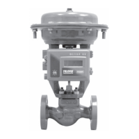
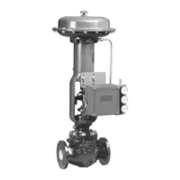
D4 Valve with easy-Drive Actuator
October 2017
10
Important Technical Notice for easyDrive Electric Actuator
When using the easyDrive electric actuator with a 420mA control signal, the unit should always have 12/24VDC
power present on the power input terminals prior to applying the 420mA signal, unless an external 250 ohm resistor
is installed per figure 4. Failure to do so could result in damage to the analog input circuitry.
It is strongly recommended to place an external 250 ohm resistor between terminals 3 and 4 when using a 4-20mA
signal to control the actuator. When the actuator is configured to 1-5V input with an external 250 ohm resistor in
place, a 4-20mA signal may be safely used without danger to input circuitry.
This order of operation must always be maintained when powering the unit on if no external 250 ohm resistor is used:
1. 12/24VDC power on
2. 420mA control signal engaged
This order of operation must always be maintained when powering the unit off:
1. 420mA control signal disengaged
2. 12/24VDC power off
The result of not following this order of operation could result in permanent damage
to the analog input circuitry. This
damage can result in the inability of the controller to see the control signal, resulting in the actuator moving the valve
plug to the loss of signal position.
Default Input Signals
The D4 with easyDrive comes from the factory calibrated and ready for use with the following default input signals
shown in table 5.
Table 5. D4 easy-Drive Default Input Signals
CONFIGURATION ON/OFF POSITIONING
Input Signal L2e (dual dry contact) 4-20 mA
If the input signal of the application matches table 5, proceed to the Wiring Instructions section. If the input signal of
the application does not match table 5, proceed to the Configuration section.
Configuration
Input Configuration
There are 2 functional configurations available for the easyDrive electric actuator: On/Off and Positioning. It is not
possible to change an actuator from On/Off to Positioning after it has been delivered from the factory. Version 4.21
and higher firmware will allow a positioning unit to be changed to on/off.
All available input signals are shown in table 6.
Table 6. All Available Input Signals
CONFIGURATION ON/OFF POSITIONING
Control Source Modbus Local Modbus Local
Input Signal Modbus
L2e Dual Dry
Contact (default)
Single Dry Contact Modbus 4-20 mA (default) 1-5 V
If you are using the default inputs signals, and the valve has not been disassembled or adjusted in any way, there is no
need to recalibrate the assembly. You can proceed directly to Startup (page 12).
 Loading...


