Instruction Manual
D103031X012
D2 FloPro Valve
June 2011
12
5. Install the male packing adaptor, lower anti-extrusion washer (key 12), and packing spacer over the valve stem as
showninfigure4.
6. Firmly press all packing parts into the packing bore with a tube.
7. Install the five Belleville springs (key 9) over the valve stem as shown in figure 4.
8. Lubricate the threads of the packing retainer with anti-seize and install into the bonnet using a 1-1/8 inch wrench.
Make sure the Belleville springs are completely enclosed by the packing retainer as shown in figure 4.
9. Torque the packing retainer to 81 NSm(60lbfSft). The packing retainer has been installed correctly when a
metal-to-metal contact has been made between the packing retainer end and the bonnet (key 2). The packing
retainer threads should be flush with the bottom of the bonnet as shown in figure 4.
10. If the bottom casing (key 20) has been removed, place O-ring (key 16) into the groove provided in the top of the
bonnet. Place the bottom casing on the bonnet, oriented in the same position as marked in step 7. on page 10.
Screw the hex nut (key 18) onto the bonnet, and tighten to 203 NSm (150 lbfSft).
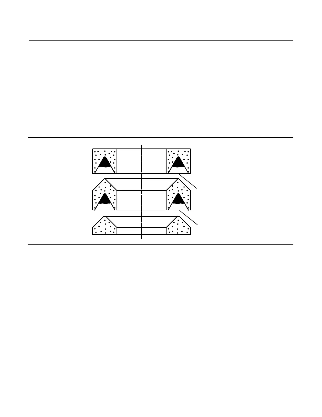
Figure 5. Lubrication Locations on Packing
FEMALE PACKING ADAPTER
MALE PACKING ADAPTER
PACKING RING
LUBRICATE WITH 3mm (1/8 INCH
BEAD) OF SUPPLIED HIGH
PERFORMANCE FLUORINATED
GREASE (KEY 44)
LUBRICATE WITH 3mm (1/8 INCH
BEAD) OF SUPPLIED HIGH
PERFORMANCE FLUORINATED GREASE
11. For air-to-open actuator action only (see figure 6), assemble the actuator by first placing the O-ring (key 37) over
the valve stem. Then place the washer (key 36) over the valve stem. Place the diaphragm (key 19) over the valve
stem, and position it so the holes in the diaphragm match the holes in the casing. Place the diaphragm plate (key
25) over the valve stem. Install the washer (key 24) and the diaphragm hex nut (key 26). Tighten the diaphragm hex
nut to 10 NSm(90lbfSin), while holding the stem by the flats. Install six springs (key 27) and attach the upper casing
(key 21) by first installing the two long cap screws (key 30) opposite one another.
12. For air-to-close actuator action only (see figure 7), assemble the actuator by first placing 2 of the springs (key 27)
from the actuator into the bottom casing (key 20), equally spaced, 180 degrees apart. Place the washer (key 36)
over the valve stem, as shown in view A of figure 7. Then place the O-ring (key 37) over the valve stem. Next install
the diaphragm plate (key 25) and, using the diaphragm plate, correctly position the actuator springs.
a. Place the diaphragm (key 19) over the stem, along with the washer (key 24). Position the diaphragm so the holes
in the diaphragm align with the holes in the bottom casing.
b. Insert a 1/8 inch diameter drift punch, or other suitabledevicethroughthe5/32inchdiameterholeinthevalve
stem located below the bottom of the previously removed flow adjuster. Install the hex nut (key 26) and tighten
to 10 NSm(90lbfSin). Use the 1/8 inch drift punch or other holding device to turn the stem to align the holes of
the diaphragm (key 19) to the lower casing (key 20).
13. Position the upper casing and install the two long cap screws (key 30) opposite one another. Install the six shorter
cap screws (key 22) and the hex nuts, tightening the actuator casing cap screws evenly using a cross-tightening
procedure. Torque to 10 NSm(8lbfSft).
 Loading...


