3
20
19
18
17
16
14
13
12
15
11
10
09
07
08
06
05
03
02
01
04
HANCOCK CAST STEEL - GATE, GLOBE AND CHECK VALVES
INSTALLATION, OPERATION AND MAINTENANCE INSTRUCTIONS
2 GATE VALVES
2.1 Installation and operation
2.1.1 Prior to installation
Valves not required for immediate use should
be stored under clean conditions to reduce the
risk of foreign matter entering the valve during
unpacking. If the valves are unpacked for
checking purposes, they should be immediately
re-packed until required for use.
Protection caps fitted to inlet and outlet
connections must be removed, but not until
immediately prior to installation.
Seating faces should be wiped clean with a
drycloth before commencing installation.
2.1.2 Installation
Valves are suitable for flow in either direction,
but they should be fitted in either horizontal
pipelines with the stem upright or vertical
lines. Other positions can be detrimental to
theproper seating of the wedge.
The valves should be installed in positions
where the minimum stress is imposed on them
from expansion and contraction of the pipe, and
pipework should be adequately supported close
to the valve to minimize mechanical pipe strain.
For bolting valves into the pipeline, see General
Installation Instructions Section 1.
All valves will have been pressure tested at
ambient temperature before delivery, so it is
recommended that gland packing nuts should
be tightened after a short time on higher
temperature service.
2.1.3 Operation
Rotation of the handwheel in the clockwise
direction (see markings) will cause the valve
to close, and vice versa. Shut off should be
achieved by application of the handwheel torque
only. Excessive application of force can result in
failure of the thrust assembly or damage to the
valve seating.
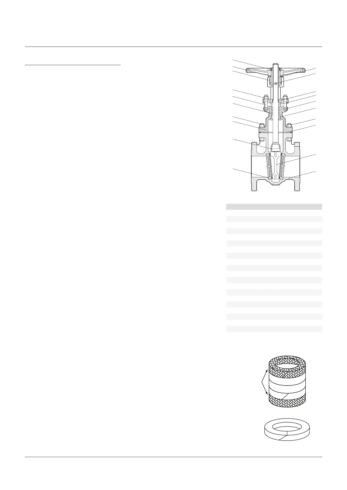
PARTS LIST
No. Description
1 Body
2 Seat ring
3 Wedge gate
4 Stem
5 Bonnet bolt
6 Bonnet nut
7 Gasket
8 Bonnet
9 Backseat
10 Packing
11 Gland eyebolt
12 Gland
13 Gland flange
14 Eyebolt nut
15 Eyebolt pin
16 Nipple
17 Stem nut
18 Yoke sleeve nut
19 Hand wheel
20 Hand wheel nut
Braided end ring
Die-formed rings
(3 min.)
Braided end ring
120° Stagger of joints
45° End cut
2.2 Maintenance
Gland leakage
CAUTION
On no account should stem gland repacking be
attempted under pressure if the contained fluid is
dangerous because of temperature, high pressure
or chemical composition.
Evenly tighten the gland adjusting nuts to
compress the packing rings.
If this does not correct the leakage or if
the adjustment is fully used up, it will be
necessaryto repack the gland using a new
set of the correct grade packing, or to add
packingring(s).
Re-packing glands
To gain access to the packing box, the gland
adjusting nuts should be removed and the
gland and packing flange removed or retracted
along the stem as far as possible. When the
stuffing box has been completely emptied of the
original packing, it must be thoroughly cleaned
before the new packing is introduced. It is
recommended that the packing manufacturers
general instructions are followed when
repacking glands.
General
It is recommended that the reconditioned valve
should be subjected to hydrostatic testing in
line, before being reinstated on line working
conditions.
2.3 Spares
The normal requirement for spare parts for
normal wear in service are gland packing
andgaskets.