5
13
12
10
9
8
11
07
06
05
04
03
01
02
HANCOCK CAST STEEL - GATE, GLOBE AND CHECK VALVES
INSTALLATION, OPERATION AND MAINTENANCE INSTRUCTIONS
4 SWING CHECK VALVES
4.1 Installation of valve
4.1.1 Prior to installation
Valves not required for immediate use should
be stored under clean conditions to reduce the
risk of foreign matter entering the valve during
unpacking. If the valves are unpacked for
checking purposes, they should be immediately
re-packed until required for use.
Protection caps fitted to inlet and outlet
connections must be removed but not until
immediately prior to installation.
Check that the disk is swinging freely on its
hinge arrangement with no hang-ups.
Seating faces should be wiped clean with a dry
clean cloth before commencing installation.
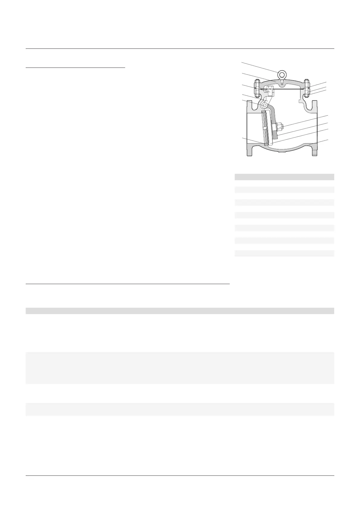
PARTS LIST
No. Description
1 Body
2 Seat ring
3 Disc
4 Lever arm
5 Nut
6 Hinge pin
7 Yoke
8 Bonnet nut
9 Bonnet stud
10 Bolt
11 Gasket
12 Cover
13 Eye bolt
5 TROUBLE-SHOOTING
The following table will cover the various problems which are common to most valves.
Theinformation provided will aid in isolating and correcting these problems.
Problem Possible cause Solution
Leakage through
thestempacking
1. Gland nuts are loose. 1. Tighten gland bolts.
2. Gland is binding against the stem or packing chamber wall. 2. Check to ensure gland is centered and evenly tightened.
3. Inadequate amount of packing rings. 3. Install additional packing rings.
4. Packing is hard and dry. 4. Replace with new packing.
5. Packing was not properly cut and staggered. 5. Replace with new packing.
6. Stem is damaged. 6. Repair or replace as required.
Problems in operating
valve
1. Stem binding during travel. 1. Remove dirt and lubricate stem with grease.
2. Stem packing is exerting excessive force on the stem. 2. Check torque on gland nuts.
3. Stem is damaged. 3. Examine stem through full open and close action.
Repairorreplaceasrequired.
4. Internal components may be damaged. 4. Disassemble the valve. Inspect and repair as needed.
Bonnet leakage 1. Bonnet nuts are loose. 1. Tighten to values as listed.
2. Gasket is damaged. 2. Disassemble and install a new gasket.
3. Flange faces are damaged. 3. Repair and install a new gasket.
Seat leakage 1. Valve not properly seated.
1. Check to see if valve is tightly closed.
2. Internal components are damaged or worn.
2. Inspect internal components and repair as required.
4.1.2 Installation
Valves are suitable for flow in one direction only
and this is shown by a direction arrow marked
on the valve body. It is essential that they are
installed in the correct flow (arrow) situation.
They may be fitted in horizontal or vertical
(flow-upwards) pipelines, or any in-between
lines with flow-upward. They must always be
orientated so that the hinge swings downwards
and with the hinge pin horizontal.
The valves should be installed in positions
where the minimum stress is imposed on them
from expansion and contraction of the pipe,
and pipe work should be adequately supported
each side of the valve to minimize mechanical
pipestrain.
4.2 Maintenance
Routine Maintenance
While the valve is working satisfactory, there
isno requirement for servicing.