Do you have a question about the Emerson HVAC Drive H300 and is the answer not in the manual?
Procedures for receiving, inspecting, and verifying package contents.
Details on identifying the unit via nameplates and understanding VFD rating labels.
Guide to decoding the electronic bypass part number for ordering and identification.
Guidelines for physically mounting the unit and ensuring proper ventilation clearances.
General safety rules and conduit requirements for wiring the unit.
Specifics on connecting incoming power and input device wiring.
Instructions for connecting motor wiring to the bypass output terminals.
Details on analog output, digital inputs, and relay outputs.
Factory wiring connections between the bypass control board and the inverter.
Guidelines for proper grounding of the electronic bypass package.
Final checks after wiring is complete before energizing the unit.
Procedures to verify correct motor rotation in both VFD and bypass modes.
Steps to check motor rotation when powered by the VFD.
Steps to check motor rotation when powered directly via bypass.
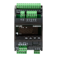
Explanation of keypad controls, buttons, LEDs, and status indicators for operation.
Step-by-step guide for initiating operation of the electronic bypass.
Procedures for safely stopping and shutting down the electronic bypass.
Description of the control board, DIP switches, and jumper settings.
Summary of the functions and indicators on the electronic bypass keypad.
How to use bypass configuration switches to tailor system behavior.
Explanation of using extra customer inputs for specific application needs.
How motor overload, system failures, and power interruptions are handled.
Explanation of operational modes like TEST, VFD, Bypass, Hand, and Auto.
Details on MANUAL, AUTOMATIC, and EMERGENCY bypass modes.
Essential parameters that must be set for proper electronic bypass operation.
Suggested parameter values for common application scenarios.
Details on Motor Overload, Safety, Fire Alarm, and VFD Faults displayed on the bypass keypad.
Key technical specifications, approvals, and design features of the bypass package.
Procedures for periodic maintenance and inspection of the electronic bypass.
A checklist for verifying proper installation before powering up the bypass.
A checklist for verifying correct VFD setup and operation.
Specific startup parameters for cooling tower fan and pump applications.
| Model | H300 |
|---|---|
| Output Voltage Range | 0 to Input Voltage |
| Cooling Method | Air-cooled |
| Overload Capacity | 150% for 60 seconds |
| Horsepower | 1 - 475 Hp |
| Amperage | Varies by model |
| Control Method | V/f Control, Sensorless Vector Control |
| Communication Protocols | Modbus RTU |
| Protection Class | IP20 |
| Enclosure | NEMA 1 |
| Protection Features | Overcurrent, Overvoltage, Undervoltage, Overtemperature |
| Communication Interfaces | RS485, Ethernet (optional) |
| Ambient Temperature Range | -10°C to 50°C |
| Enclosure Rating | IP20 |
| Input Voltage | 200-240 VAC ±10%, 380-480 VAC ±10%, 500-600 VAC ±10% |
| Power Range | 0.75 - 355 kW (1 - 475 Hp) |