www.Fisher.com
Single Point Calibration
Fisher
™
FIELDVUE
™
DVC6200 HW2 Digital Valve
Controller
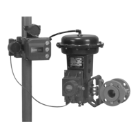
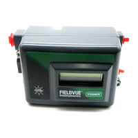
The Single Point Calibration procedure allows you to replace an existing positioner with a DVC6200 HW2, on
sliding-stem applications, without performing a travel calibration. This procedure should only be used in emergency
situations where a positioner must be completely replaced and is part of a valve assembly that does not have a process
bypass or the process cannot be shut down. For other procedures, refer to the DVC6200 Quick Start Guide and the
DVC6200 HW2 Instruction Manual.
Related Documents
D Fisher FIELDVUE DVC6200 Series Digital Valve Controllers Quick Start Guide (D103566X012)
D Fisher FIELDVUE DVC6200 HW2 Digital Valve Controller Instruction Manual (D103605X012
)
These documents are available from your Emerson sales office
or at Fisher.com.
WARNING
Personal injury or property damage, caused by unexpected valve movement and an uncontrolled process, could result if
this procedure is attempted when the valve is not locked at its present position. If you cannot safely lock the valve in
position until this procedure is complete, do not proceed with this procedure.
Notes
This procedure should only be used in emergency situations where a positioner must be completely replaced and is part of a valve
assembly that does not have a process bypass or the process cannot be shut down. Do not proceed if the valve has a bypass or the
process can be shut down.
The valve will need to be locked at its present position. This can be accomplished by using a handwheel or other mechanism. If the
valve assembly or valve application will not allow you to safely lock the valve in position until this procedure is complete, do not
proceed with this procedure.
This procedure can be used to replace a positioner with a DVC6200. The DVC6200 used to replace the existing positioner must
have firmware 2, 3, 4, 5, 6, or 7, hardware 2 and HC, AD, or PD diagnostic tiering. Do not proceed with this procedure if the digital
valve controller does not meet the tiering and firmware requirements mentioned above.
This procedure can only be performed on sliding-stem valve assemblies and only supports feedback connections using the linear
sliding-stem arrays. This procedure cannot be performed with a long stroke roller array. Do not proceed if you have something
other than a sliding-stem valve assembly with a linear sliding-stem array.
The Single Point Calibration procedure cannot be completed with Pressure Control. Do not proceed with this procedure if the
Travel/Pressure Control Mode is Pressure.
This procedure is not recommended for a valve assembly with a double-acting actuator that uses a DVC6200 with a Relay A that
was previously configured for a valve assembly with a single-acting actuator.
This procedure requires the use of ValveLink
™
software 13.5 or newer.
DVC6200 Digital Valve Controller
January 2020
Instruction Manual Supplement
D104490X012


 Loading...