2
3
12
13
10
11
2
7
6
1
4
5
80 62.7
100 167
125 200
150 200
200 303
250 395
300 400
ASSEMBLY INSTRUCTIONS
NOTE: When installing new parts supplied by
Emerson, all machine surfaces are coated with Pro-
Coat to prevent rust. This coating can easily removed
with paint thinner.
1. Make sure the lower trunnion hole is free
ofany foreign matter.
2. Using the proper bearing installation tool
(relative to the size of the valve) tap lower
bearing into body bore flush withinside
machined counter bore on bottom
ofvalvebody.
3. Verify that lower plug trunnion if free
offoreign matter.
4. Lubricate lower plug trunnion diameter
witha coat of lubricant-never-seize.
5. Place lower spacer (9) on lower trunnion
up to the rubber coated portion of
plug. Thelower spacer should be with
counter bore facing away from rubber
coatedportion.
6. Lubricate lower packing and grit excluder(8)
with a coat of lubricant-silicone grease.
7. Place lower packing and grit excluder (8)
on lower trunnion so that it will seat in the
groove of the spacer.
8. Make sure the inside diameter of the
lower bearing (5) is clean and free of dirt,
gritorany other foreign matter.
9. Install plug into valve body by placing
the lower trunnion into the bearing that
has been placed in bottom of valve body.
Turnplug while forcing down until plug
bottoms out.
10. Lubricate upper plug trunnion with a coat
oflubricant-never-seize.
11. Place upper spacer (9 on upper inset)
onupper trunnion up to the rubber coated
portion of plug.The upper spacer should
be with counter bore facing away from
therubber coated portion.
12. Lubricate upper packing (grit excluder) (8)
with a coating of lubricant-silicone grease.
13. Place upper packing (grit excluder) (8)
onthe upper trunnion so that it will seain
the groove of the spacer.
14. Place upper bearing (4) on the upper
trunnion until it shoulders against the upper
spacer.
15. Lubricate cap o-ring (6) with a coating of
lubricant-silicone grease and fit cap o-ring
in valve body cap counter bore.
16. Install cap (3) over plug stem rotating
clockwise to ensure proper orientation.
17. Insert cap screws (7) into cap holes and
tighten by hand. Use appropriate torque
wrench and a diagonal pattern to tighten
cap screws to the recommended torque
value (appropriate for the valve size)
listedbelow
RECOMMENDED CAP SCREW TORQUES
Valve size DN Torque (Nm)
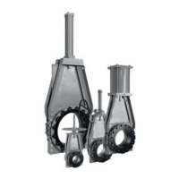
KEYSTONE FIGURE 580 AND 583 BALLCENTRIC VALVES
INSTALLATION AND REPAIR INSTRUCTIONS
DISASSEMBLY INSTRUCTIONS
CAUTION
Never attempt to remove or perform maintenance
on a valve that is pressurized and ensure that
pipeline is isolated.
ACTUATOR REMOVAL
All figure 580/583 valves allow for direct
mounting of actuators/gear operators.
Removalof these may be accomplished by
removing the mounting bolts used to hold the
actuator on the top plate of the valve and then
sliding the entire actuator assembly off of the
valve stem.
1. On DN 150 and smaller valves, open
valvefully.
2. Remove cap screws (7) in a diagonal
pattern.
3. Lift cap (3) away from valve body.
NOTE: When cap is removed from body, plugwill
remain attached to cap.
4. Using a rubber mallet, drive plug (2)
outofcap (3).
5. Remove o-ring (6) from valve body cap
counter bore.
6. Remove packing (12) and grit excluder.
7. Remove upper spacer (9) from upper plug
trunnion.
8. Remove retaining ring (11)
fromstemgroove.
NOTE: Care should be taken when removing
retaining ring. Use properly sized circlip pliers and
wear appropriate safety glasses.
9. Remove bushing (10) from upper plug stem.
10. Remove stem packing seal (12) from upper
plug stem.
11. Remove lower packing and grit excluder (8).
12. Remove lower spacer (9) from
lowerplugtrunnion.
13. Check that bearings are not unduly pitted,
galled or worn. If so, they will require
replacement.
14. Using a bearing puller if required, pull the
lower bearing (4) from the body bore and
thetop bearing from the cap bore.
15. If the lower bearing cannot be easily
removed, fill the stem hole with grease
and drive a plug of the same diameter
as the stem into the bearing bore.
The hydraulic forces generated will push
out the lower bearing. Thoroughly clean all
components and inspect all metal parts and
valve bore for corrosion. Checktheplug
for nicks or wear on the rubber seating
surface. Checkall packing for cuts or
deformation. Replace any parts needed.
The seat area ofthe body should be
inspected carefully fordamage.
 Loading...