5-3 A81N0EA
5. [CUTOFF]
Press [1] button to select “COR” for Red Cutoff
adjustment. Press [3] button to select “COB” for
Blue Cutoff adjustment.
[DRIVE]
Press [4] button to select “DR” for Red Drive
adjustment. Press [6] button to select “DB” for Blue
Drive adjustment.
6. In each color mode, press [CH. o / p] buttons to
adjust the values of color.
7. Adjust Cutoff and Drive so that the color
temperature becomes 11000K (x
=
0.279 / y
=
0.272 ±0.005).
The following adjustment normally are not attempted in
the field. Only when replacing the LCD Panel then adjust
as a preparation.
5. White Balance Adjustment
[Component / DTV]
Purpose: To mix red, green and blue beams correctly
for pure white.
Symptom of Misadjustment: White becomes bluish
or reddish.
1. Operate the unit for more than 20 minutes.
2. Input the White Purity.
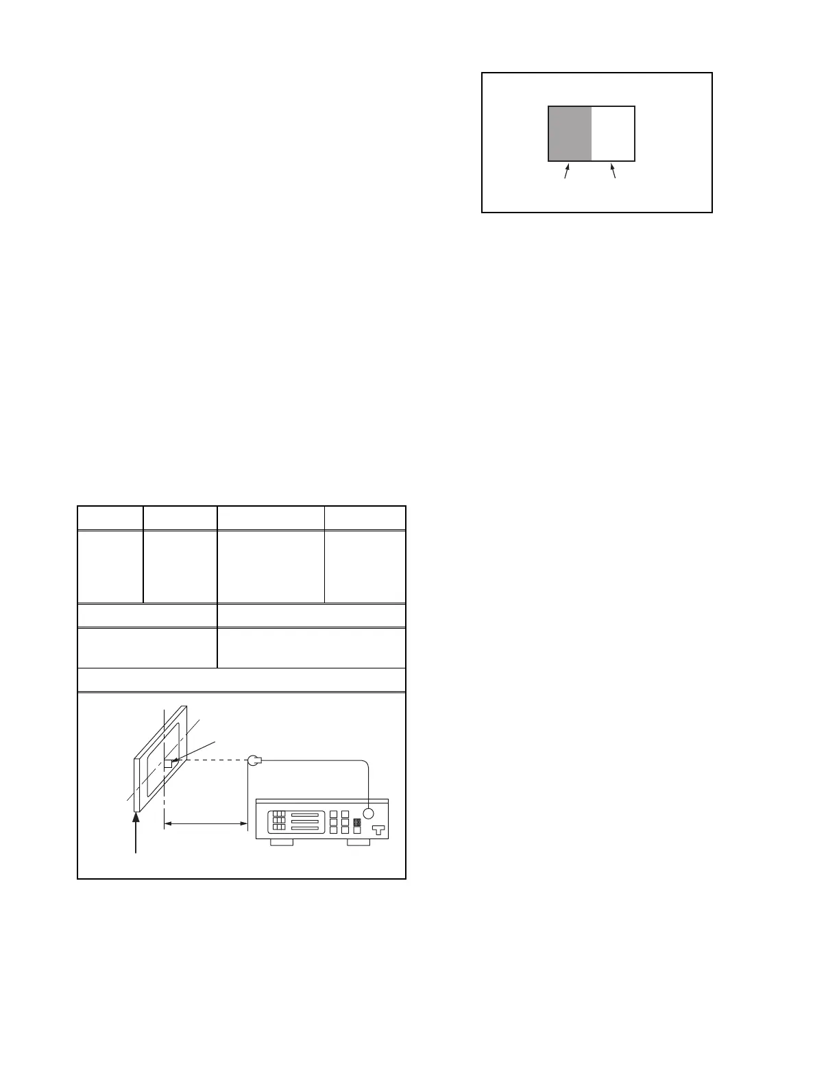
3. Set the color analyzer to the CHROMA mode and
bring the optical receptor to the center on the
LCD-Panel surface after zero point calibration as
shown above.
Note: The optical receptor must be set
perpendicularly to the LCD Panel surface.
4. Enter the Service mode. Press [VOL. n] button on
the service remote control unit and select “C/D2”
mode.
5. [CUTOFF]
Press [1] button to select “COR” for Red Cutoff
adjustment. Press [3] button to select “COB” for
Blue Cutoff adjustment.
[DRIVE]
Press [4] button to select “DR” for Red Drive
adjustment. Press [6] button to select “DB” for Blue
Drive adjustment.
6. In each color mode, press [CH. o / p] buttons to
adjust the values of color.
7. Adjust Cutoff and Drive so that the color
temperature becomes 11000K (x
=
0.279 / y
=
0.272 ±0.005).
Test Point
Adj. Point Mode Input
Screen
[CH. o/p]
buttons
[VIDEO]
C/D2
White Purity
(APL 70%)
or
(APL 30%)
M. EQ. Spec.
Pattern Generator,
Color analyzer
x= 0.279 ± 0.005
y= 0.272 ± 0.005
Figure
Color Analyzer
It carries out in a darkroom.
L = 3 cm
Perpendicularity
INPUT: WHITE 70%, 30%
30%=30IRE
70%=70IRE
INPUT SIGNAL
 Loading...