7-6
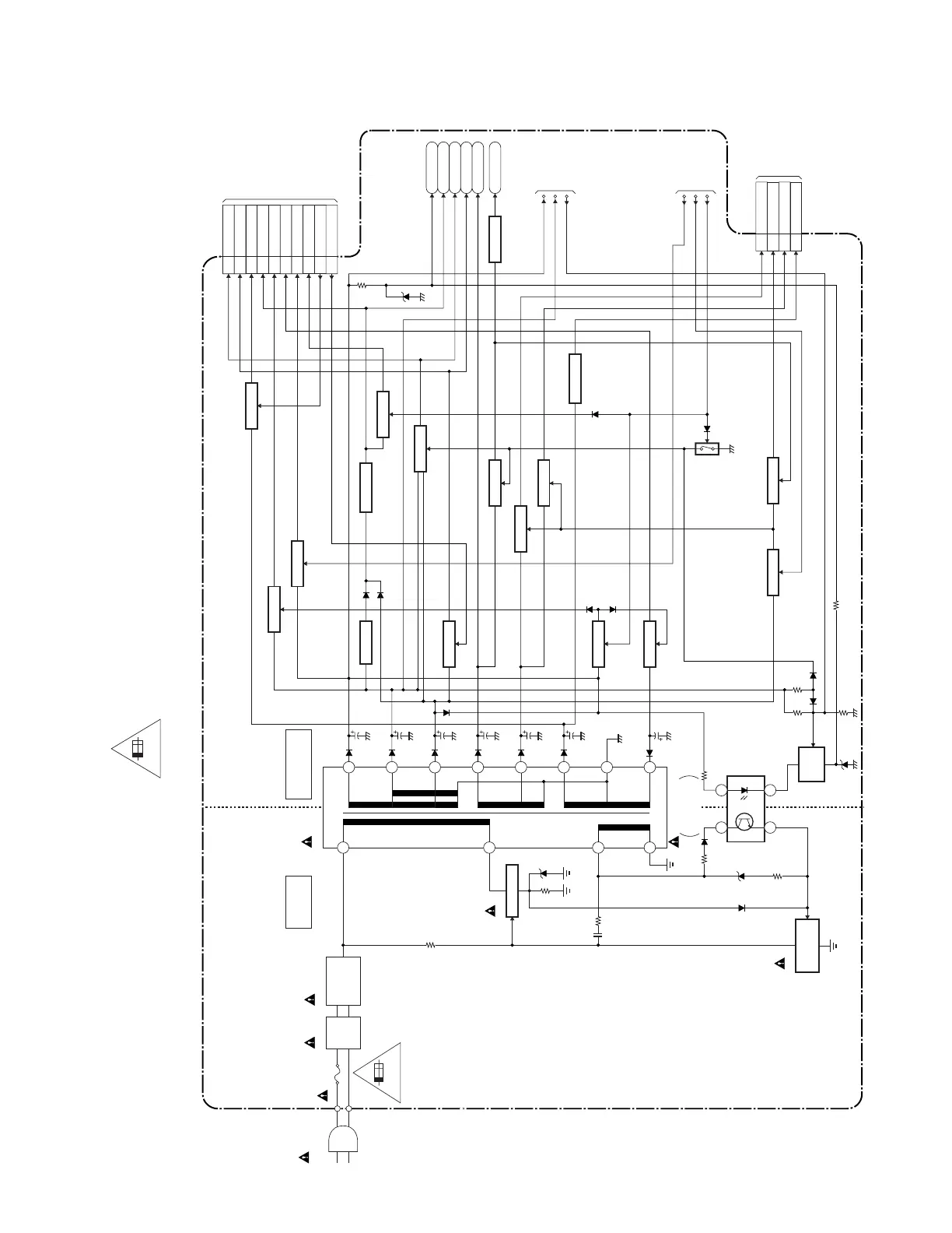
Power Supply Block Diagram
A81N0BLP
4A/125V
F601
4A/125V
LINE
FILTER
L601
AC601
AC CORD
BRIDGE
RECTIFIER
D605 - D608
HOT COLD
T601
16
9
12
13
14
4
4
3
1
2
IC601
ERROR
VOLTAGE DET
Q601
Q603
SWITCHING
CONTROL
SWITCHING
MAIN CBA
2
7
6
+12V
P-ON+5V
AL+3.3V
P-ON+3.3V
INV+22V
+35V
P-ON+9V
VT+33V
DTV-ON-H
P-ON-H1
VGH-H
HOT CIRCUIT. BE CAREFUL.
15
11
Q913
FEED
BACK
TO DIGITAL MAIN
CBA UNIT
(CN1501)
10
P-ON+5V6
CN701
P-ON+3.3V
8,9
P-ON+1.5V
12,13
AL+3.3V14
LCD+13V16
LCD-6.8V18
LCD+24.5V20
LCD+3.3V23
POW-CONT219
POW-CONT117
TO DTV
MODULE
CBA UNIT
(CN101,
CN102)
DTV-ON+2.5V
20
CN61
DTV-ON+5V
5
DTV-ON+3.3V
19
DTV-ON+1.8V
21
TO SYSTEM
CONTROL
BLOCK
DIAGRAM
TO LCD
BACKLIGHT
BLOCK
DIAGRAM
Q932,Q933
SW+24.5V
IC908,Q910,
Q919,Q922
SW+1.5V
IC905
+5V REG.
IC904
+1.8V REG.
IC909,Q901
+3.3V REG.
IC912,Q909
SW+2.5V
IC913,Q935
SW+13V
Q917,Q928
SW+3.3V
Q926,Q927
SW+5V
Q905,Q906
SW+7V
Q907
SW+5V
IC910,Q902,
Q924,Q925
SW+3.3V
Q923
SW+12V
Q934
SW-6.8V
Q918
Q916
+9V REG.
IC911,Q908
SW+3.3V
Q929,Q930
SW
OVER CURR. DET
CAUTION !
Fixed voltage (or Auto voltage selectable) power supply circuit is used in this unit.
If Main Fuse (F601) is blown , check to see that all components in the power supply
circuit are not defective before you connect the AC plug to the AC power supply.
Otherwise it may cause some components in the power supply circuit to fail.
For continued protection against risk of fire,
replace only with same type 4 A, 125V fuse.
CAUTION ! :
ATTENTION : Utiliser un fusible de rechange de même type de 4A, 125V.
4A/125V
NOTE:
The voltage for parts in hot circuit is measured using
hot GND as a common terminal.
 Loading...