3
Installation
The basic installation procedure of parallel system is
the same as that for single module system. The
following sections only introduce the installation
procedures specific to the parallel system.
Cabinet Installation
Parallel system composed of two UPS modules
The two UPS modules that will form the 1+1 system
should be placed side-by-side. Each battery cabinet
is placed next to its corresponding UPS module.
Preliminary Checks
Each UPS module should have the same rating, the
same firmware and the same hardware version.
Refer to the instructions in Conditions for
Parallel System on page 1.
Protective Devices
Refer to the instructions in the Liebert NX
installation manual, SL-25215.
Power Cables
Wiring of power cables is similar to that of single
module system (see the Liebert NX installation
manual, SL-25215). The bypass sources of all
modules should be the same, and the outputs should
be connected altogether correctly.
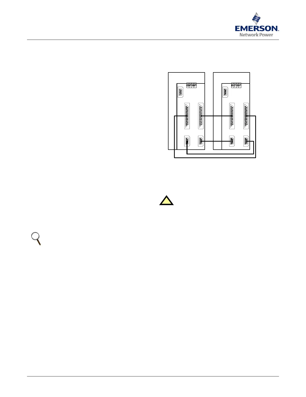
Parallel Control Cables
Make the connections below on the parallel logic
board (M3) inside the Liebert NX:
• Connect one end of the DB-25 interconnecting
cable to the X2_1 connector of UPS 1 and the other
end to the X2_2 connector of UPS 2.
• Connect one end of the DB-25 interconnecting
cable the X2_2 connector of UPS 1 and the other
end to the X2_1 connector of UPS 2.
• Connect one end of the DB-9 interconnecting cable
the X1_1 connector of UPS 1 and the other end to
the X1_2 connector of UPS 2.
• Connect one end of the DB-9 interconnecting cable
the X1_2 connector of UPS 1 and the other end to
the X1_1 connector of UPS 2.
The connections are shown in Figure 2.
Figure 2 Connecting 1+1 system parallel control
cables
Commissioning a Parallel System
Check the input and output wiring of each UPS
module. Ensure that the phase rotation sequence of
the main inputs and the bypass inputs and outputs
of each UPS module are the same. Ensure that the
parallel cables are connected firmly.
It is assumed that the installation is complete, the
system has been commissioned by authorized
personnel and the external power isolators are
closed. Disconnect the load before startup.
Start the UPS modules separately and set the
parameters of each UPS module through
configuration software. Pay particular attention to
the parameters relevant to the parallel system:
• UPS Configuration: Each UPS module
belonging to the parallel system should be set as
Parallel configuration.
• UPS ID No.: Each UPS module should have a
unique identification number in the parallel
system.
• Parallel system requisite UPS units: Set the
minimum number of UPS modules to support the
expected load. For 1+1 systems this must be set
to 1.
NOTE
The length and specifications of power
cables including the bypass input cables and
UPS output cables should be the same so the
load can be shared evenly in bypass mode.
!
CAUTION
The operations in this section must be
performed by authorized electricians or
qualified technical personnel. If you have
any difficulties, contact Emerson Network
Power Liebert Services at 800-543-2378.
#1 UPS Module #2 UPS Module
Parallel BoardParallel Board
X5
X4
X4
X2-1 X2-1 X2-2X2-2
X1-1 X1-1 X1-2X1-2
4
12
1 & 2 - UPS Unit
3 - Parallel Connection Board
4 - Interconnecting Cables
3

 Loading...