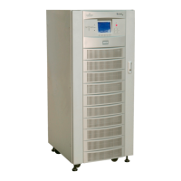
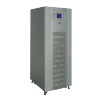
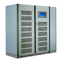
Do you have a question about the Emerson Liebert NX 10-30kVA and is the answer not in the manual?
Defines symbols used in the manual for electrical safety and equipment identification.
Procedures for inspecting UPS equipment and shipping containers for damage upon arrival.
Visual examination of UPS and battery equipment for transit damage and checking nameplate details.
Guidelines for storing equipment indoors if immediate installation is not possible, considering humidity and temperature.
Initial checks before proceeding with installation, including identification of the UPS unit.
Considerations for selecting an appropriate location for the UPS, including environmental and airflow requirements.
Criteria for choosing a UPS location, focusing on accessibility, ventilation, and environmental conditions.
Detailed environmental requirements for UPS operation, including temperature, humidity, and ventilation clearances.
Specific placement advice for 1+N parallel systems to ensure optimal performance and grounding.
Guidance on safely moving the UPS and optional battery cabinets, including weight and tipping hazards.
Physical construction details of the NX UPS, including frame, panels, doors, and casters.
Required space around the UPS for installation, servicing, and air circulation.
Instructions for bolting the equipment to the floor or mounting it on a pedestal for raised floors.
Methods and considerations for routing cables into the NX UPS from the top or bottom.
Guidelines for positioning and connecting optional Maintenance Bypass and Battery cabinets relative to the UPS.
Guidance on selecting and installing power cables for the UPS system, considering voltage, current, and environment.
Factors for sizing UPS input, bypass, output, and battery cables based on current and voltage requirements.
Explains split bypass (dual-input) vs. single-input configurations and how to wire them.
General recommendations for cable sizing, neutral cable, grounding, and conduit usage.
Detailed instructions for connecting rectifier input, bypass, output, and external battery busbars.
Importance of proper grounding for safety, EMI reduction, and bonding all cabinets.
Requirements for installing circuit breakers in input AC supply and battery cabinets for safety.
Step-by-step procedure for connecting power cables, including common and dual input configurations.
Overview of the monitor board's capabilities for managing the UPS, battery system, and communication.
Details the available input dry contacts at the X3 slot for alarms and external signals.
Lists the terminal functions for the Maintenance Bypass Cabinet interface.
Describes the terminal connections for the Battery Circuit Breaker (BCB) box interface.
Explains the output dry contact relays at the X1 slot for status signaling.
Instructions for connecting the Emergency Power Off (EPO) input for both older and newer firmware versions.
Recommends matching battery types and fitting isolating devices for parallel battery sets.
Emphasizes extreme care when working with batteries due to high voltage and potential hazards.
Information on internal batteries being shipped charged, requiring a recharge before use.
Discusses cabinet sizes, handling, inspection, storage, and general installation precautions for external cabinets.
Discusses cabinet sizes, handling, inspection, storage, and general installation precautions for external cabinets.
Procedures for routing battery power and control cables to the UPS cabinet, considering floor or adjacent installations.
Details on cabinet positioning, bolting, service clearance, cable routing, software setup, and tray support.
Step-by-step guide to connecting the battery cabinet to the UPS, including ground, battery cables, and control cables.
Requirements for using non-matching battery cabinets, including disconnect switches and ventilation.
Describes the function of the bypass switch for transferring loads between UPS and bypass source.
Explains the operation when the bypass switch is in the normal position, with the UPS powering the load.
Describes bypass mode, providing an alternate power path but without UPS protection for the load.
Details maintenance mode, offering an alternate power path with no UPS protection and no power to the UPS.
Guidance on positioning the Maintenance Bypass Cabinet relative to the UPS or as a standalone unit.
Procedures for installing cables in the Maintenance Bypass Cabinet, including wiring preparation.
Precautions and steps before wiring, including removing cover plates and ensuring proper tools.
Referencing tables for selecting cables and notes on earth leakage currents.
Step-by-step guide for connecting input and output wiring, including conduit and access plates.
Instructions for aligning and bolting the Maintenance Bypass Cabinet to the UPS cabinet.
Explains the Load Bus Synchronizer (LBS) for synchronizing UPS outputs in parallel systems.
Conditions under which the DBS (LBS) operates, including master/slave states.
Details on the LBS cable connection and configuration for NX-to-NX dual bus setups.
Guide to setting up parallel UPS modules for increased reliability and serviceability.
Introduction to the NX's parallel operation technology and the benefits of 1+N systems.
Highlights features of parallel systems, including hardware, firmware, and paralleling logic.
Explains redundancy paralleling and how the system maintains operation during module failures or load increases.
Summarizes the different operation modes for parallel systems (Normal, Battery, Bypass, Maintenance Bypass).
Procedures for installing parallel UPS systems, covering conditions, cabinet installation, and checks.
Prerequisites for parallel systems, including matching ratings, firmware, and bypass sources.
Guidelines for placing UPS modules and paralleling cabinets in a parallel system.
Verifying that each UPS module meets the conditions for parallel operation.
Guidance on protective devices for each UPS and the overall parallel system.
Details on wiring power cables for parallel systems, including routing and termination.
Instructions for connecting parallel control cables in a ring configuration for reliability.
Explains how to connect external EPO facilities for parallel systems, similar to single units.
Describes the function and types of battery circuit breaker boxes for protection and isolation.
Lists standards and certifications the UPS system complies with.
Specifies the environmental conditions under which the UPS can operate without degradation.
Details the physical dimensions, weight, heat dissipation, and airflow of the UPS.
Provides detailed electrical specifications including input, output, and battery parameters.
Lists the approved battery manufacturers and models used in the NX UPS.
Electrical specifications related to the input rectifier, including voltage, current, and power factor.
Specifications for the DC intermediate circuit, including battery voltage and current.
Electrical characteristics of the inverter output, including voltage, power, and regulation.
Electrical specifications for the bypass input, including voltage tolerance and overload capacity.
Illustrates the front and left side dimensions and key features of the UPS cabinet.
Continues dimensional views, showing top and bottom layouts of the UPS cabinet.
Identifies the main internal and external components of a typical UPS unit.
Diagrams showing AC output, input, neutral, earth, and battery cable connection points.
Illustrates the placement and dimensions of internal batteries within the UPS cabinet.
Shows the wiring schematic for connecting batteries in layers within the cabinet.
Diagrams and table detailing how to interconnect battery cabinets with the UPS module.
Illustrates the cabling connections between the UPS module and the Maintenance Bypass Cabinet.
Shows wiring diagrams for 1+1 parallel cabinet configurations.
Details the lineup and wiring for a SlimLine distribution cabinet connected to the NX.
Illustrates connections for a 1+N Type A parallel system configuration.
Details connections for a 1+N Type A1 parallel system configuration.
Shows wiring for a 1+N Type B parallel system configuration.
Illustrates connections for a 1+N Type B1 parallel system configuration.
Details wiring for a 1+N Type C parallel system configuration.
Shows connections for a 1+N Type C1 parallel system configuration.
Illustrates wiring for a 1+N Type D parallel system configuration.
Diagrams showing possible cabinet lineups involving SlimLine components.
Provides tables for lug sizes and torque specifications for various electrical connections.
Detailed torque specifications for nut and bolt combinations and compression lugs.
Torque ratings for battery terminal connections, both initial and annual.
Table providing distances from floor or top of unit to internal UPS connection points for cable length calculation.
| Power Rating/Capacity/Output Power Capacity | 10-30 kVA |
|---|---|
| Frequency | 50/60 Hz |
| Topology | Double Conversion Online |
| Efficiency | Up to 96% |
| Battery Type | Valve Regulated Lead Acid (VRLA) |
| Phase | 3-phase |
| Communication Ports/Interface | RS-232, USB |
| Operating Temperature | 0 to 40 °C |
| Operating Humidity | 0 to 95% (non-condensing) |
