Safety
Information
Product
information
Mechanical
Installation
Electrical
installation
Getting
started
Basic
parameters
Running the
motor
Optimization
SMARTCARD
operation
Onboard
PLC
Advanced
parameters
Technical
data
Diagnostics
UL
information
Mentor MP User Guide 71
Issue: 3 www.controltechniques.com
The encoder supply voltage present on the drive encoder connector is
defined by this parameter as 0 (5V), 1 (8V), 2 (15V) or 3 (24V)
The following encoders can be connected to the drive encoder port.
0, Ab: Quadrature incremental encoder, with or without marker pulse.
1, Fd: Incremental encoder with frequency and direction outputs, with or
without marker pulse.
2, Fr: Incremental encoder with forward and reverse outputs, with or
without marker pulse.
The terminations may be enabled/disabled by this parameter as follows:
Provided the set-up parameters for the drive encoder are correct this
parameter shows the encoder speed in rpm.
It should be noted that the value shown by this parameter is measured
over a 16ms sliding window period (in the same way as di05 (Pr 0.40,
3.02)), and so the ripple in this parameter accessible via comms or by an
option module is as defined for di05 (Pr 0.40, 3.02). The FI attribute for
this parameter is set, and so further filtering is applied when this
parameter is viewed with one of the drive keypads.
6.1.9 I/O
The following modes are available for the analog input 3. A current loop
loss trip is generated if the input current falls below 3mA. In modes 4 and
5 the analog input level goes to 0.0% if the input current falls below 3mA.
In modes 2 and 4 the destination parameter is at a value equivalent to
0.0% when the input current is less than 4mA. In modes 3 and 5 the
destination parameter is at a value equivalent to 100.0% when the input
current is less than 4mA.
When analog input 3 is in thermistor mode the display indicates the
resistance of the thermistor as a percentage of 10kΩ.
OFF (0) = Terminal inactive
On (1) = Terminal active
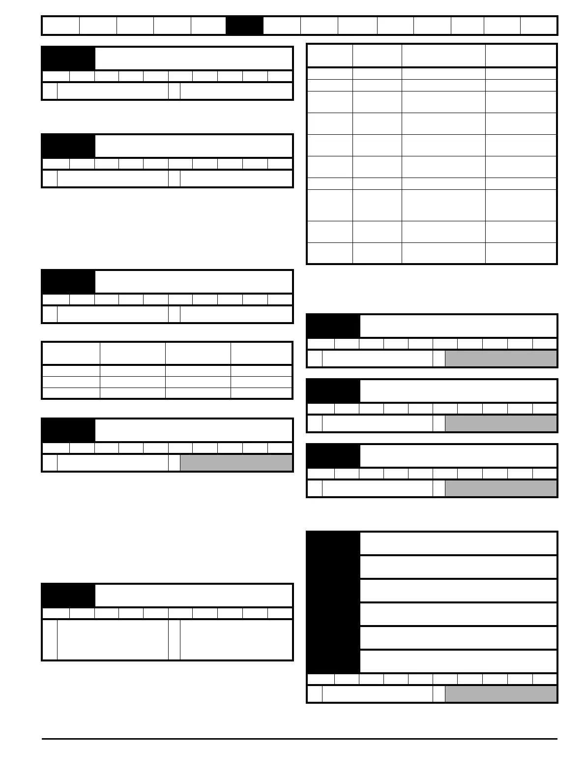
Fb06
{0.76, 3.36}
Drive encoder supply voltage
RW Txt US
Ú
5V (0), 8V (1), 15V (2), 24V (3)
Ö
5V (0)
Fb07
{0.77, 3.38}
Drive encoder type
RW Txt US
Ú
Ab (0), Fd (1), Fr (2)
Ö
Ab (0)
Fb08
{0.78, 3.39}
Drive encoder termination select
RW Uni US
Ú
0 to 2
Ö
1
Encoder
input
Fb08
{0.78, 3.39} = 0
Fb08
{0.78, 3.39} = 1
Fb08
{0.78, 3.39} = 2
A-A\ Disabled Enabled Enabled
B-B\ Disabled Enabled Enabled
Z-Z\ Disabled Disabled Enabled
Fb09
{0.79, 3.27}
Drive encoder speed feedback
RW Bi FI NC PT US
Ú
±10,000.0 rpm
Ö
in01
{0.81, 7.15}
Analog input 3 mode
RW Txt US
Ú
0-20 (0), 20-0 (1), 4-20.tr (2),
20-4.tr (3), 4-20 (4), 20-4 (5),
VOLt (6), th.SC (7), th (8), th.
diSp (9)
Ö
Eur: th (8), USA: VOLt (6)
Parameter
value
Parameter
string
Mode Comments
0 0-20 0 - 20mA
1 20-0 20 - 0mA
2 4-20.tr
4 -20mA with trip on
loss
Trip if I < 3mA
3 20-4.tr
20 - 4mA with trip on
loss
Trip if I < 3mA
44-20
4 - 20mA with no trip
on loss
5 20-4
20 - 4mA with no trip
on loss
0.0% if I < 4mA
6 VOLt Voltage mode
7th.SC
Thermistor with short
circuit detection
TH trip if R > 3k3
TH reset if R < 1k8
THS trip if R < 50R
8th
Thermistor without
short circuit detection
TH trip if R > 3k3
TH reset if R < 1k8
9th.diSp
Thermistor display
only with no trip
in02
{0.82, 7.01}
Analog input 1
RO Bi NC PT
Ú
±100.00 %
Ö
in03
{0.83, 7.02}
Analog input 2
RO Bi NC PT
Ú
±100.0 %
Ö
in04
{0.84, 7.03}
Analog input 3
RO Bi NC PT
Ú
±100.0 %
Ö
in05
{0.85, 8.01}
T24 digital I/O 1 state
in06
{0.86, 8.02}
T25 digital I/O 2 state
in07
{0.87, 8.03}
T26 digital I/O 3 state
in08
{0.88, 8.04}
T27 digital input 4 state
in09
{0.89, 8.05}
T28 digital input 5 state
in10
{0.90, 8.06}
T29 digital input 6 state
RO Bit NC PT
Ú
OFF (0) or On (1)
Ö