NetSure
™
-48V DC Power System
User Instructions, UM582127000 (Issue AD, January 20, 2014)
Spec. No: 582127000 Code: UM582127000
Model No: 721NPBB Issue AD, January 20, 2014
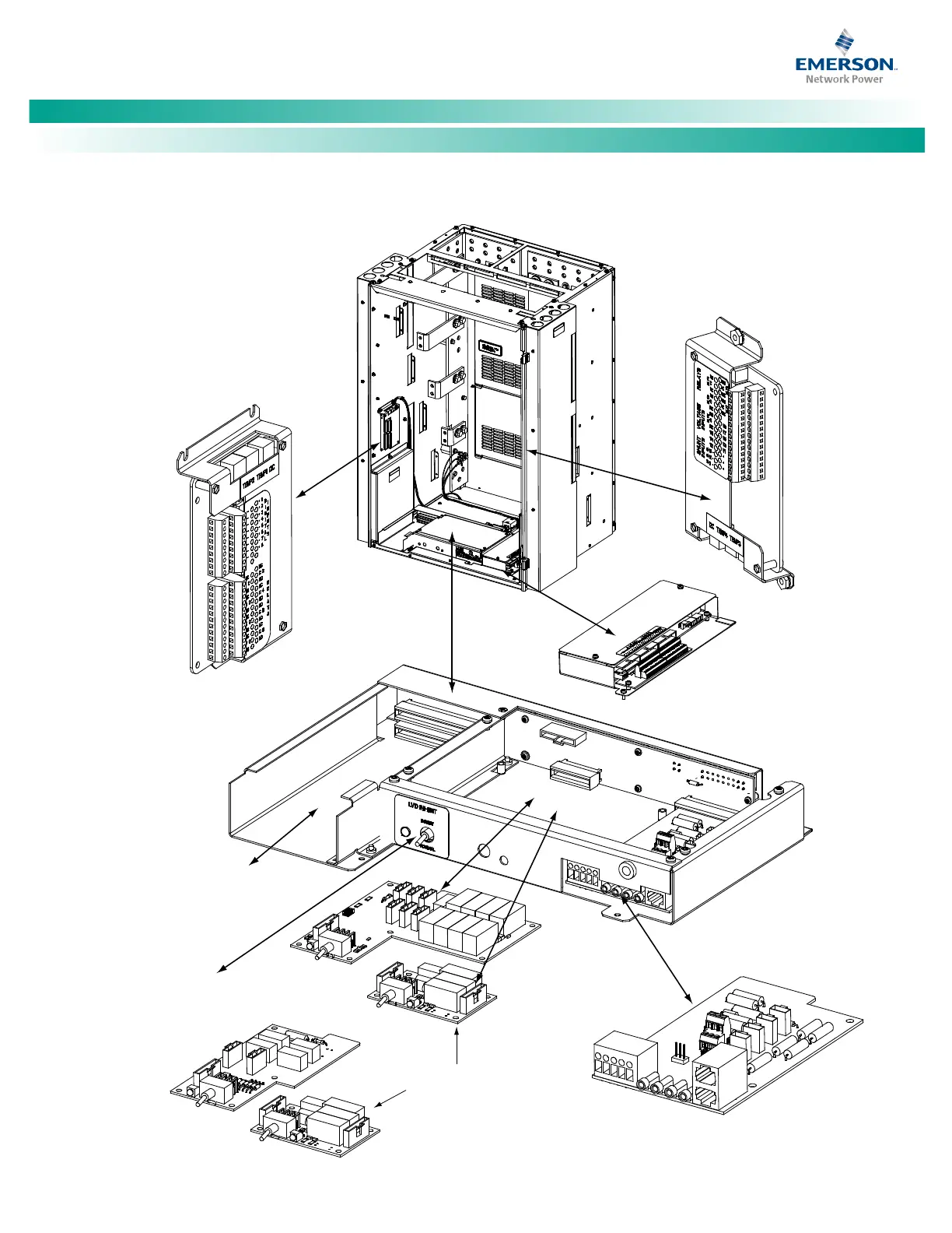
Figure 1. Circuit Card Locations
IB2 (Main Bay Only)
(ACU+ Interface Board)
(located on inside side panel)
Optional EIB (Main Bay Only)
(ACU+ Extended Interface Board)
(located on inside side panel)
Optional SM-DU+ and
Shunt Interface Board
4-Row Cabinet Shown,
Others Similar
(Front Door Removed in
Illustration for Clarity)
System Interface
Circuit Card
OR
Optional LVD
Driver Circuit Card
Optional LVD Driver
Lite Circuit Card
ACU+ Controller
(Main Bay)
SM-DU
(Supplemental Bays)
Mounting Position
Optional Manual Battery
Disconnect Circuit Card
(Main Bay Only)
Optional LVD
Inhibit Switch
(factory installed
if option specified)

 Loading...