9
emersonfans.com
Please contact 1-800-654-3545 for further assistance
U.L. Model No.: 42-CL
3. Ceiling Fan Assembly (Continued)
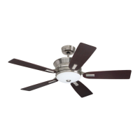
3.11
Position the Switch Housing Assembly on the Switch
Housing Plate and align the holes in the Switch Housing
Assembly with the holes in the Plate.
Secure the Switch Housing Assembly by reinstalling
the Three Mounting Screws (previously removed)
(Figure 11).
SWITCH HOUSING
ASSEMBLY
REINSTALL
MOUNTING
SCREWS (3)
Figure 11
Do not pinch wires between the switch housing
assembly and the switch housing plate.
WARNING
!
BLADE
ASSEMBLY
TIGHTEN TWO
CAPTIVE SCREWS
PER FLANGE
Figure 13
3.13
NOTE: Take care not to scratch fan housing when
installing blades.
Attach one Blade Assembly to the Motor Hub, securely
tightening the Two M5 x 13 mm Captive Screws
assembled in the Flange (Figure 13).
Repeat this procedure for the other Four Blade
Assemblies.
A spare M5 x 13 mm Screw is supplied in parts bag,
if needed.
You have now completed the assembly of your new
Ceiling Fan. You can now proceed with hanging and
wiring your Fan.
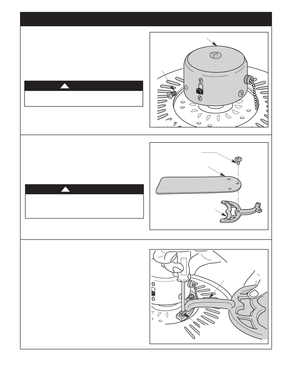
3.12
Mount the Blade Flange to the Fan Blade using Three
M5 x 6 mm Washer Head Screws (supplied)
(Figure 12).
Repeat this procedure for other Four Fan Blades and
Blade Flanges.
A spare M5 x 6 mm Washer Head Screw is supplied in
parts bag, if needed.
FAN BLADE
BLADE FLANGE
M5 x 6 mm WASHER
HEAD SCREW (3)
Figure 12
To reduce the risk of personal injury, do not bend
the blade flange when installing the blade flanges,
balancing the blades or cleaning the fan. Do not insert
foreign objects in between rotating fan blades.
WARNING
!