3
OVERPRESSURE PROTECTION
The recommended safety pressure limitations are stamped
on the valve label.
Downstream overpressure protection shall be also provided
if the inlet pressure can be greater than the PS (see label).
Equipment’s operation below the maximum pressure
limitations does not preclude the possibility of damage from
external sources or debris in the line.
The relief valve should be inspected for damage after any
overpressure condition.
TRANSPORT AND HANDLING
Established transport and handling procedures shall be
followed to avoid any damage on the pressure containing
parts by shocks or anomalous stresses.
Ringbolts are designed just for handling of equipment
weight.
Built-up sensing lines and pressure accessories (e.g. pilots)
shall to be protected by shocks or anomalous stresses.
ATEX REQUIREMENTS
If the provisions of EN 12186 & EN 12279, national
regulations, if any, and specic manufacturer
recommendations are not put into practice before
installation and if purge by inert gas is not carried out before
equipment’s start-up and shut-down operations, a potential
external and internal explosive atmosphere can be present
in equipment & gas pressure regulating/measuring stations/
installations.
If a presence of foreign material in the pipelines is foreseen
and purge by inert gas is not carried out, the following
procedure is recommended to avoid any possible external
ignition source inside the equipment due to mechanical
generated sparks:
• drainage to safe area via drain lines of foreign materials, if
any, by inow of fuel gas with low velocity in the pipe-work
(5m/sec)
In any case,
• provisions of Directive 1999/92/EC and 89/655/EC shall
be enforced by gas pressure regulating/measuring station/
installation’s end user
• with a view to preventing and providing protection against
explosions, technical and/or organizational measures
appropriate to the nature of the operation shall be taken
(e.g. : lling/exhausting of fuel gas of internal volume
of the isolated part/entire installation with vent lines
to safe area - 7.5.2 of EN 12186 & 7.4 of EN 12279 ;
monitoring of settings with further exhaust of fuel gas to
safe area ; connection of isolated part/entire installation to
downstream pipeline; ….)
• provision in 9.3 of EN 12186 & 12279 shall be enforced
by pressure regulating/measuring station/installation’s end
user
• external tightness test shall be carried out after each
reassembly at installation site using testing pressure in
accordance with national rules
• periodical check/maintenance for surveillance shall be
carried out complying with national regulations, if any, and
specic manufacturer recommendations.
OPERATION
V/50 and V/60 Series
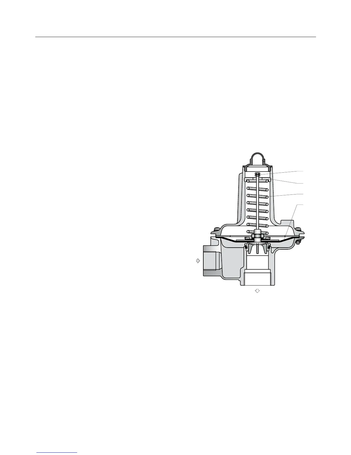
Figure 3. Closed V/50 Relief Valve
Whenever gas pressure under diaphragm (D) is higher than
the force exerted by spring (M), diaphragm is raised causing
sleeve (O), which is integral with the diaphragm itself, to
move and thereby open the release orice.
In order to check the efciency of the relief valve, pull up
valve opening stem (S).
Valve setting is carried out by adjusting the compression of
spring (M) through the appropriate ring (G).
Valve set point should generally be at an intermediate value
between active regulator or monitor and slam-shut valve
(if tted) set points.
In all other cases, it is recommended that relief valve be set
at a value at least 15% higher than the working pressure of
the equipment.
 Loading...