G1
G2
G3
G4
H1
H2
H3
H4
I1
I2
I3
I4
J1
J2
J3
J4
K1
K2
K3
K4
L1
L2
L3
L4
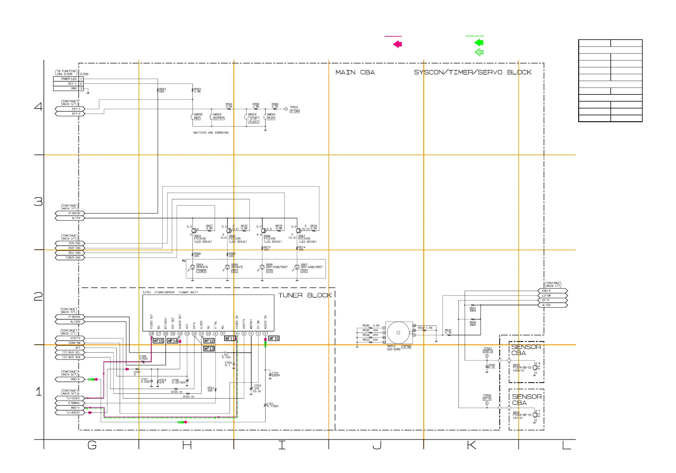
DVD AUDIO SIGNAL
PB AUDIO SIGNAL
DVD VIDEO + PB VIDEO SIGANL
REC AUDIO SIGNAL
REC VIDEO SIGNAL
Main 2/7 Schematic Diagram < VCR Section >
1-11-5
1-11-6
H94X1SCM2
Note:
When it is necessary to replace one or more of the following Diodes,
all four should be replaced: D564, D565, D566, D567.
*
1
MAIN 2/7
Ref No. Position
Q563 H-3
Q565 H-3
Q566 I-3
Q567 I-3
CL509 G-4
TP502 I-4
TP506 K-1
TP507 K-1
TEST POINTS
CONNECTOR
TRANSISTORS