Do you have a question about the Emerson Unidrive M400 Series and is the answer not in the manual?
Manufacturer liability, installation, and specification changes without notice.
Verifying drive firmware versions for compatibility with existing systems.
Commitment to minimizing environmental impacts and product recycling.
Compliance with REACH regulation regarding Substances of Very High Concern (SVHC).
Guidance on using the manual with the Power Installation Guide for configuration and operation.
Information essential for avoiding safety hazards and product damage.
High voltage hazards and precautions when working with the drive.
Importance of correct installation and system design to prevent hazards.
Compliance with instructions regarding transport, storage, installation, and use.
Drive access must be restricted to authorized personnel.
Drive enclosure is not a fire enclosure; a separate enclosure must be provided.
Installer responsibility for regulations, wiring, fuses, and grounding.
Recommendations for motor installation, shaft exposure, and speed capabilities.
Brake control functions are not for safety; independent devices are required.
Parameters have profound effects; careful consideration is needed.
Drive presents a falling or toppling hazard; handle with care.
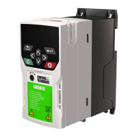
Overview of the Unidrive M400 AC drive for open loop AC drive applications.
Explains the formation of model numbers for the Unidrive M range and identification labels.
Details Heavy Duty and Normal Duty ratings, differentiating continuous and overload limits.
Describes Open loop mode (vector, V/F) and RFC-A mode for induction motor control.
Information on using the keypad and display for drive status and parameter changes.
Explanation of the typical drive rating labels and date code format.
Identifies various options available for the drive, including keypads and adaptors.
Step-by-step guide for installing and removing SI option modules and keypads.
Procedure for replacing the battery in keypads that feature a real-time clock.
Details the functions and specifications of the 24 Vdc backup supply.
Explains how to establish EIA 485 serial communications using an AI-485 adaptor.
Describes the single insulated nature of the serial port and available comms leads.
Details the various control terminal functions and wiring requirements for inputs and outputs.
Explains the CI-Keypad display, its status states, and how to configure displayed parameters.
Details the functions of keypad control buttons and display formats.
Describes the drive's parameter menus, navigation, and access levels.
Allows direct access to parameters without scrolling through menus.
Describes shortcuts for navigating parameter menus and editing values.
Details the advanced menus, parameter groups, and option module menus.
Lists and explains the various mnemonics and status indications displayed by the drive.
Explains how alarms are indicated by alternating display strings and lists common alarm types.
Procedure for changing the drive's operating mode (e.g., Open-loop, RFC-A).
How to save parameter changes made in advanced menus to non-volatile memory.
Procedure for resetting parameters to their factory default values.
Explains parameter access levels and user security settings to control visibility and editability.
Explains how parameter ranges depend on other settings, drive rating, and operating mode.
Lists and describes commonly used parameters for basic drive setup and configuration.
Outlines the minimum control connection requirements for different drive control methods.
Procedure for changing the drive's operating mode (e.g., Open-loop, RFC-A).
Step-by-step procedure for basic drive setup and commissioning for open loop mode.
Step-by-step procedure for basic drive setup and commissioning for RFC-A mode.
Details essential motor parameter settings for open loop and RFC-A control modes.
Explains stationary and rotating autotune tests for optimizing motor parameter measurements.
Details voltage modes for motor control: vector control (Ur S, Ur I, Ur, Ur_Auto) and fixed boost.
How to enable slip compensation to prevent speed droop in open loop mode.
Essential motor parameter settings for RFC-A mode, including current, voltage, speed, poles, and power factor.
Details stationary, rotating, and mechanical load autotune tests for RFC-A mode.
Explains how proportional (Kp) and integral (Ki) gains control current loop response for dynamic applications.
Explains proportional (Kp), integral (Ki), and differential (Kd) gains for frequency controller response.
Specifies how maximum motor rated current is determined for different drive sizes.
Details parameters controlling motoring, regenerating, and symmetrical current limits.
Explains the motor thermal model, protection accumulator, and how settings affect protection.
Discusses the default switching frequency and its increase, affecting drive and motor heating.
How to run an induction machine above synchronous speed into the constant power region.
States the drive's maximum output frequency limit.
Explains how over-modulation affects output voltage and machine current.
Explains Modbus register addressing, PLC registers, and CT parameter mapping.
States minimum data consistency for parameters.
Explains Modbus RTU data encoding (big-endian).
Lists supported Modbus function codes for reading and writing registers.
Overview of the NV Media Card feature for simple configuration and backup.
Details limitations and file types recognized by the drive when using an SD card.
Describes methods for writing parameters and user programs to an NV Media Card.
Explains how to transfer data from an NV Media Card to the drive.
Lists potential trips related to NV Media Card operations and their recommended actions.
Details header information stored on NV Media Cards for data blocks.
Describes the drive's ability to store and execute PLC programs using Machine Control Studio.
Highlights advantages of combining Onboard PLC and Machine Control Studio for replacing PLCs.
Details features of the Onboard PLC, including tasks, variables, custom menus, and limitations.
Lists all menus and their general descriptions for parameter reference.
Explains the coding system used in parameter tables for read/write status, data types, etc.
Details the logic diagram and parameters related to setting the drive's frequency reference.
Explains the logic diagram and parameters for configuring acceleration and deceleration ramps.
Details the logic diagram and parameters for open-loop frequency control.
Details the logic diagram and parameters for torque and current control in open-loop mode.
Explains the open-loop logic diagram and parameters related to motor control settings.
Details the logic diagram and parameters for sequencer functions and real-time clock settings.
Explains the logic diagram and parameters for configuring analog inputs and outputs.
Explains the logic diagrams and parameters for configuring digital inputs and outputs.
Details logic diagrams and parameters for programmable logic, motorized pots, binary sums, and timers.
Covers general drive settings like serial communications, security, and NV Media Card configurations.
Explains logic diagrams and parameters for threshold detection, variable selection, and brake control.
Details the logic diagram and parameters for configuring the User PID controller.
Covers parameters common to all option modules and lists available option modules and their categories.
Lists application menu parameters for read-write and read-only integers and bits.
Lists application menu parameters for read-write long integers.
Details parameters specific to a second motor configuration, including current, voltage, and gains.
Allows configuration of Menu 0 parameters for specific functions.
Explains the different status modes displayed on the keypad and LED indicators.
Details how trips are indicated, including trip strings, sub-trip numbers, and LED status.
Explains how to identify the source of a trip using sub-trip numbers (xxyzz format).
Lists common trips and their associated sub-trip numbers and reasons, with recommended actions.
Describes internal faults (HFxx) indicating irrecoverable errors and potential hardware failures.
Explains how alarms are displayed and lists common alarms that may require action to prevent trips.
Provides a table of status indications displayed on the drive.
Explains how the drive logs the last ten trips, including date, time, and sub-trip numbers.
Provides the UL file reference numbers for the drive and Safe Torque Off function.
States that all supplied option modules, kits, and accessories are UL Listed.
Describes the UL enclosure ratings for drives as supplied and with accessories.
Information on drive mounting options including surface, bookcase, and tile mounting.
Specifies required environment conditions and operating temperature limits.
Covers terminal torque, wiring terminals, branch circuit protection, and dynamic braking.
| Overload | 150% for 60 seconds |
|---|---|
| Frequency Range | 0 to 400 Hz |
| Communication Protocols/Options | EtherNet/IP, Profibus, CANopen |
| Enclosure Type/Rating | IP20 |
| Switching Frequency | 2 kHz to 16 kHz |
| Output Voltage | 0 to Input Voltage |
| Protection Features | Overcurrent, Overvoltage, Undervoltage, Short Circuit |
| Storage Temperature | -40°C to 70°C (-40°F to 158°F) |
| Humidity | 95% RH (non-condensing) |
| Altitude | Up to 1000 m |