Unidrive M / HS Frame 7 to 10 Power Installation Guide 67
Issue Number: 5
Safety information Product information Mechanical installation
Electrical installation
Technical data UL listing information
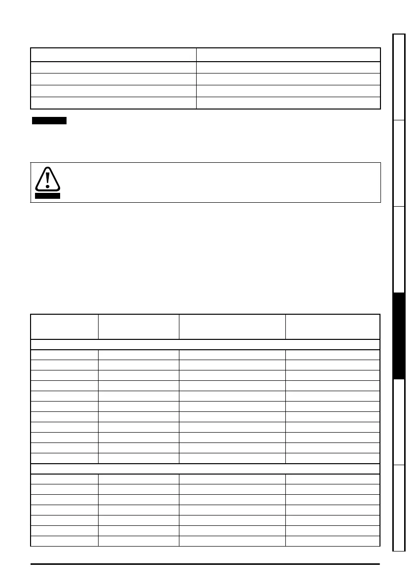
Table 4-6 Braking transistor turn on voltage
4.9.1 External braking resistor
When a braking resistor is to be mounted outside the enclosure, ensure that it is mounted in a
ventilated metal housing that will perform the following functions:
• Prevent inadvertent contact with the resistor
• Allow adequate ventilation for the resistor
When compliance with EMC emission standards is required, external connection requires the cable
to be armored or shielded, since it is not fully contained in a metal enclosure. See section
4.12.5 Compliance with generic emission standards on page 72 for further details.
Internal connection does not require the cable to be armored or shielded.
Table 4-7
Minimum resistance values and peak power rating for the braking resistor at 40 °C (104 °F)
Drive voltage rating DC bus voltage level
200 V 390 V
400 V 780 V
575 V 930 V
690 V 1120 V
When a braking resistor is used, Pr 00.015 (Pr 00.028 on Unidrive M200 to M400) should
be set to FASt ramp mode.
Overload protection
When an external braking resistor is used, it is essential that an overload protection device
is incorporated in the braking resistor circuit; this is described in Figure 4-11 on page 69.
Model
Minimum resistance
*
Instantaneous power rating Continuous power rating
Ω kW kW
200 V
07200610 4.5 37.6 15
07200750 4.5 37.6 18.5
07200830 4.5 37.6 22
08201160 2.3 73.5 30
08201320 2.3 73.5 37
09201760 (9A) 2 84.5 45
09202190 (9A) 2 84.5 45
09201760 (9E) 1.4 120.8 45
09202190 (9E) 1.4 120.8 55
10202830 1.7 99.5 75
10203000 1.7 99.5 90
400 V
07400660 7.5 90.2 30
07400770 7.5 90.2 37
07401000 7.5 90.2 45
08401340 6.3 107.4 55
08401570 6.3 107.4 75
09402000 (9A) 3.6 187.8 90
09402240 (9A) 3.6 187.8 110
Unidrive M frame7 to 10 Power Installation Guide issue5.book Page 67 Tuesday, May 24, 2016 11:52 AM
 Loading...


