EasyManua.ls Logo

Emerson White Rodgers 1E30N-910 - User Manual

Emerson White Rodgers 1E30N-910
4 pages
Print Icon
To Next Page IconTo Next Page
Loading...
YOUR THERMOSTAT REPLACES
System Models
Standard Heat Only Systems
1E30N-910
1E50N-301
Electric Furnace
Heat Pump (No Aux or Emergency Heat)
Gas or Oil Heat
Millivolt Heat Only Systems
1
PREPARATIONS
Assemble tools required: power drill, fl at blade screwdriver, wire cutter/stripper, level.
Failure to follow and read all instructions carefully before installing or op-
erating this control could cause personal injury and/or property damage.
2
THERMOSTAT FEATURES
Captive
screws
Mounting
Screw
Mounting
Screw
COVER
THERMOSTAT
BASE
WALLPLATE
SWITCHING
SUBBASE
S
Y
S
T
E
M
O
F
F
H
E
A
T
G
W
RH
Mounting
Screw
50
60
70
80
90
50
60
70
80
90
4
Figure 1. Thermostat with subbase or wallplate
To prevent electrical shock and/or equipment damage, disconnect electrical
power to the system at the main fuse or circuit breaker until installation is
complete.
CAUTION
!
Before removing wires from old thermostat’s switching subbase, label each wire with
the terminal designation it was removed from.
1. Remove Old Thermostat: A standard thermostat consists of three basic parts:
a. The cover, which may be either a snap-on or hinge type.
b. The base, which is removed by loosening all captive screws.
c. The switching subbase, which is removed by unscrewing the mounting
screws that hold it on the wall or adaptor plate.
Make a note here of the anticipator setting on the old thermostat
for future reference and use in step 5.
The heat anticipator pointer, if adjustable, will be set at one of a series of numbers
representing the current rating of the primary control in your furnace. The number will
be one of the following: .2, .4, .8, etc. or 0.2, 0.4, 0.8, etc.
3
REMOVING OLD THERMOSTAT
Installation Instructions for:
Vertical
Snap Action
1E30N-910
1E50N-301
Question and Answer IconNeed help?

Do you have a question about the Emerson White Rodgers 1E30N-910 and is the answer not in the manual?

Overview

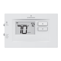
This document provides installation and operation instructions for White-Rodgers thermostats, specifically models 1E30N-910 (Vertical) and 1E50N-301 (Snap Action). These thermostats are designed to replace standard heat-only systems, electric furnaces, heat pumps (without auxiliary or emergency heat), gas or oil heat, and millivolt heat-only systems.

Function Description

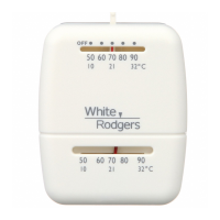
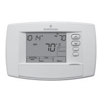
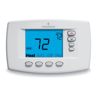
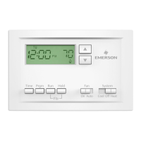
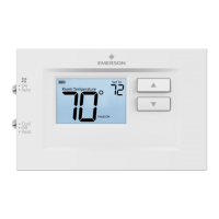
The White-Rodgers thermostat is a control device used to regulate heating systems. It senses the ambient room temperature and activates or deactivates the heating system to maintain a desired setpoint. The device features a system switch to select between heating and off modes.

Important Technical Specifications

Electrical Data:

  • Switch Rating: 24 VAC (30 VAC max.)
  • Heating Current: 0.15 to 1.2 Amps
  • Anticipator Rating (Heating): Adjustable from 0.15 to 1.2 Amps

Thermal Data:

  • Temperature Range: 50°F to 90°F (10°C to 32°C)
  • Operating Humidity Range: 0 – 90% noncondensing

The thermostat operates on a single transformer heating system, as illustrated in the typical wiring diagram. It includes a heat anticipator, which is adjustable, to optimize heating cycle rates.

Usage Features

Installation:

  1. Preparation: Before installation, gather necessary tools including a power drill, flat blade screwdriver, wire cutter/stripper, and a level. It is crucial to disconnect electrical power to the system at the main fuse or circuit breaker to prevent electrical shock or equipment damage.
  2. Removing Old Thermostat:
    • First, label each wire with its terminal designation before disconnecting it from the old thermostat's switching subbase.
    • A standard thermostat typically consists of a cover (snap-on or hinge type), a base (removed by loosening captive screws), and a switching subbase (removed by unscrewing mounting screws).
    • Note the anticipator setting of the old thermostat for future reference, as this setting (e.g., .2, .4, .8, or 0.2, 0.4, 0.8) represents the current rating of the primary control in the furnace.
    • Mercury Warning: This product does not contain mercury. However, if replacing an old thermostat that does contain mercury, handle it with care. Mercury is a toxic substance. If a cell becomes damaged, do not touch any spilled mercury. Wear non-absorbent gloves, pick up spilled mercury and place it into a container which can be sealed. If a cell becomes damaged, the unit should be discarded. Mercury must not be discarded in household trash. Contact White-Rodgers.com for location to send product containing mercury.
  3. Mounting and Wiring:
    • WARNING: Disconnect power before wiring to prevent electrical shock or equipment damage. Do not short out terminals on gas valve or primary control to test, as this can cause personal injury or property damage.
    • The thermostat installation and all components must conform to Class II circuits per the NEC code.
    • Remove Base or Wallplate: Loosen the screws on the base and remove.
    • Mount Switching Subbase or Wallplate: Use the screws provided to mount the subbase or wallplate to the wall (see Fig. 1). Two-wire systems (Heat Only) attach one wire to RH and one wire to W.
    • Mount Thermostat Base: Gently push excess wire back into the wall opening and plug hole with a fire-resistant material, such as fiberglass insulation, to prevent drafts from affecting thermostat operation. Mount the thermostat base to the subbase or wallplate using the three captive screws in the thermostat base (see Fig. 1). Tighten the screws securely.
  4. Set Heat Anticipator:
    • The heat anticipator must be set to match the current rating stamped on your main heating control. This setting is crucial for proper heating cycle length.
    • The anticipator is adjustable from 0 to 1.2 amps by rotating the contact arm (see Fig. 2). The anticipator setting is indicated by the numbers on the base that the pointer points to. If unsure, contact the thermostat manufacturer for a recommended setting.
    • For longer heating system cycles, move the anticipator clockwise to shorten heating cycles. Adjustments should not be greater than 1/2 marking at a time.
    • For millivolt operation, rotate the contact arm to the millivolt link.
    • Snap the cover on: Carefully align the cover with the base and snap the cover onto the base.

Operation:

  • Once power is turned on, simply use the system switch to select "HEAT" for heating or "OFF" to turn the heating system off.

Maintenance Features

Troubleshooting: The manual provides a comprehensive troubleshooting guide for common issues:

  • No Heat/No Fan:
    • Blown fuse or tripped circuit breaker: Replace fuse or reset breaker.
    • Furnace power switch to OFF: Turn switch to ON.
    • Furnace blower compartment door or panel loose: Replace door panel to engage safety interlock.
  • No Heat:
    • Pilot light not lit: Re-light pilot.
    • Broken or melted anticipator wire: Check system for excessive current or dead short.
    • Loose connection to thermostat or system: Verify secure connections.
    • Thermostat or heating system requires replacement or service: Test heating system; if capable, replace thermostat.
    • System Switch not set to Heat: Set to Heat and raise temperature.
  • Intermittent Heat:
    • Furnace Lock-Out Condition: Many furnaces have safety devices that shut down the system. Contact furnace manufacturer or service person.
  • Heat or Fan Runs Constantly:
    • Possible short in wiring, thermostat, or heat/cool/fan system: Check wire connections for neatness and no extra wire sticking out.
  • Furnace Cycles Too Fast or Too Slow (Narrow or Wide Temperature Swing):
    • Adjust the anticipator setting (Step 5). The anticipator setting is the only adjustment affecting the heating cycle rate. Location of thermostat, system size, and current draw can influence the cycle rate.
  • Thermostat Setting and Thermometer Disagree:
    • Thermostat thermometer setting requires adjustment or setting lever needs calibration.
    • The thermometer pointer screw (inside the front cover) can be adjusted with a slotted screwdriver. For setting lever calibration, contact a service person.
  • Adjusting Thermometer:
    • The thermometer is factory calibrated but can be adjusted with a slotted screwdriver by turning the thermometer pointer screw inside the front cover.

Homeowner Help Line: For further assistance, a homeowner help line is available at 1-800-284-2925.

White-Rodgers is a division of Emerson Electric Co. The Emerson logo is a trademark and service mark of Emerson Electric Co.

Emerson White Rodgers 1E30N-910 Specifications

General IconGeneral
BrandEmerson
ModelWhite Rodgers 1E30N-910
CategoryThermostat
LanguageEnglish

Related product manuals