EasyManua.ls Logo

Emerson White Rodgers 1F80-0224 User Manual

Emerson White Rodgers 1F80-0224
12 pages
To Next Page IconTo Next Page
Page #1 background imageLoading...
Page #1 background image
This thermostat is intended for use with a low voltage NEC
Class II system. Do not use this thermostat with a line voltage
system. If in doubt about whether your wiring is millivolt, line,
or low voltage, have it inspected by a qualifi ed heating and air
conditioning contractor or electrician.
Do not exceed the specifi cation ratings.
All wiring must conform to local and national electrical codes
and ordinances.
This control is a precision instrument, and should be handled
carefully. Rough handling or distorting components could
cause the control to malfunction.
Blue 2” Single Stage Thermostat
Installation and Operating Instructions
Save these instructions for future use!
FAILURE TO READ AND FOLLOW ALL INSTRUCTIONS
CAREFULLY BEFORE INSTALLING OR OPERATING THIS
CONTROL COULD CAUSE PERSONAL INJURY AND/OR
PROPERTY DAMAGE.
APPLICATIONS
For use with the following Class II systems:
• Single Stage systems
Single-stage heat pump systems with no Aux heat
DO NOT USE WITH:
Systems exceeding 30 VAC and 1.5 amps
3-wire zoned hydronic heating systems
1F80-0224 Thermostat
Model Programming Choices
1F80-0224
24-hour Programmable
SPECIFICATIONS
Electrical Rating:
Battery Power ................................................. mV to 30 VAC, 50/60 Hz or DC
Input-Hardwire ................................................ 20 to 30 VAC
Terminal Load ........................................................ 1.0 A per terminal, 1.5A maximum all terminals combined
Setpoint Range ...................................................... 45° to 90°F (7° to 32°C)
Differential (Single Stage) ...................................... Heat 0.6°F; Cool 1.2°F (adjustable)
Differential (Heat Pump) ........................................ Heat 1.2°F; Cool 1.2°F (adjustable)
Operating Ambient ................................................. 32° to +105°F (0° to +41°C)
Operating Humidity ................................................ 90% non-condensing max.
Shipping Temperature Range ................................ -40° to +150°F (-40° to +65°C)
Dimensions Thermostat ......................................... 3-3/4”H x 4-3/4”W x 1-1/2”D
PRECAUTIONS
To prevent electrical shock and/or equipment damage,
disconnect electric power to system at main fuse or
circuit breaker box until installation is complete.
CAUTION
!
Do not use on circuits exceeding specifi ed voltage.
Higher voltage will damage control and could cause
shock or fi re hazard.
Do not short out terminals on gas valve or primary
control to test. Short or incorrect wiring will damage
thermostat and could cause personal injury and/or
property damage.
Thermostat installation and all components of the
system shall conform to Class II (current limited)
circuits per the NEC code. Failure to do so could cause
a fi re hazard.
WARNING
!
www.white-rodgers.com
PART NO. 37-7014B
Replaces 37-7014A
0924
Question and Answer IconNeed help?

Do you have a question about the Emerson White Rodgers 1F80-0224 and is the answer not in the manual?
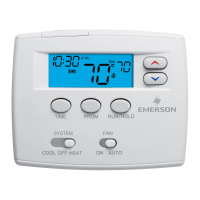
Emerson White Rodgers 1F80-0224 Specifications

General IconGeneral
DisplayDigital
Stages1 Heat / 1 Cool
Voltage24 VAC
BacklightYes
Power SourceBattery
MountingWall-mounted

Summary

APPLICATIONS

SPECIFICATIONS

PRECAUTIONS

INSTALLATION

REMOVE OLD THERMOSTAT

Steps to remove the existing thermostat before installation.

ATTACH THERMOSTAT BASE TO WALL

Instructions for mounting the new thermostat base to the wall.

O/B TERMINAL SWITCH SELECTION

How to set the O/B switch for heat pump changeover relay operation.

GAS/ELEC SWITCH

Setting the GAS/ELEC switch for system type (heat pump or single stage).

BATTERY LOCATION

Information on locating and installing batteries, and battery status indicators.

ENERGY MANAGEMENT RECOVERY (EMR)

WIRING DIAGRAMS

THERMOSTAT QUICK REFERENCE

The Thermostat Buttons and Switches

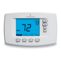
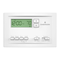
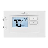
Identifies and explains the function of each button on the thermostat.

The Display

Explains the various icons and indicators shown on the thermostat display.

INSTALLER/CONFIGURATION MENU

System Configuration

Configures system type (Single Stage or Heat Pump).

CS (Cool Savings™)

Manages temperature adjustments for energy saving during high demand.

Energy Management Recovery

Enables the thermostat to start heating/cooling early to meet setpoint time.

Select Cycle Rate Selection

Adjusts anticipation and cycle rate for heating and cooling stages.

OPERATION

CHECK THERMOSTAT OPERATION

Steps to verify the correct functioning of the thermostat and HVAC system.

MANUAL OPERATION

How to manually set and override temperature settings for heating or cooling.

PROGRAMMING

PROGRAMMING YOUR THERMOSTAT

Guidelines for planning thermostat programming for comfort and efficiency.

Planning Your Program

Advice on how to plan your program based on occupancy and needs.

Entering Your Program

Step-by-step guide to setting up custom heating and cooling schedules.

Set Current Time and Day

Instructions for setting the current time and day on the thermostat.

Enter Heating Program

Detailed steps for programming the heating schedule periods and temperatures.

Enter Cooling Program

Steps to program the cooling schedule using the same method as heating.

CHECK YOUR PROGRAMMING

How to verify the programmed heating and cooling schedules are correctly set.

TROUBLESHOOTING

Reset Operation

Procedure to reset the thermostat after display or operation issues.

Related product manuals