- 9V +
NECK
VOLUME
OUTPUT
T
R
S
OUTPUT CABLE
BRIDGE
VOLUME
NOTE REVERSED
CONNECTOR!
BATTERY
BUSS
BRIDGE PICKUP
NECK PICKUP
EXG
CONTROL
Diagram #4
Volume / Volume
EXB Control
VOLUME
B122rH
TONE
B124rH
VOLUME
B122rH
VOLUME
B122rH
VOLUME
B122rH
MASTER
TONE
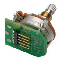
Like all EMG Accessory products the EXG uses the 5-pin header as a standard.
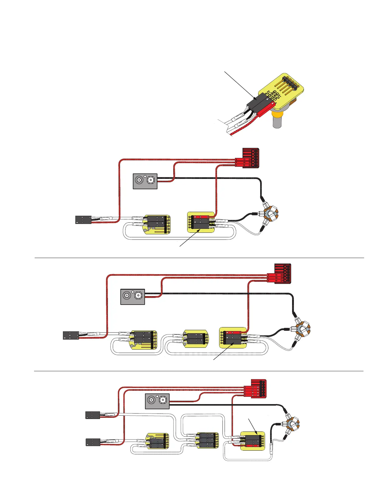
Diagram #1 to the right shows how the plug-in connectors are installed.
Be sure to reverse the input connector as shown.
Since there are a variety of installations in which the EXG can be installed it
is impossible to show every installation in this data sheet. Some of the simpler
installations have been chosen. More diagrams are available at our website
http://www.emgpickups.com.
Diagrams #2 and #3 illustrate installations that have a single pickup and
do not use a selection switch.
Page 3 has diagrams that have 2 pickups and a selection switch.
Page 4 has diagrams that have 3 Pickups and use the B161 five-position
selection switch/buss. If you have the B161, refer to that data sheet where
more options regarding 3-pickup instruments are available.
Keep in mind that all of the EMG Accessory controls can be substituted for one
another since they all have buffered inputs and utilize the same 5-pin connnector.
So, if you decide you would rather use the SPC instead of the EXG, simply unplug
the EXG and replace it with the SPC.
Installation Instructions:
EMG Model: EXG
EXG Page 2
Diagram #1
Note: Reversed connector! Pins 1 and 2 are reversed.
Make sure the connectors are plugged on as shown.
All of the EMG Active controls use the same 5-pin connector
shown below.
Diagram #2
One Pickup
One Volume
One EXB
OUTPUT
T
R
S
FROM PICKUP
BATTERY
NEG (-)
RED
RED
BATTERY
BUSS
OUTPUT CABLE
MASTER
VOLUME
- 9V +
EXG Control
RED
MASTER TONE
(PASSIVE)
Diagram #3
One Pickup
One Volume
One Master Tone (Passive)
One EXB
OUTPUT
T
R
S
FROM PICKUP
BATTERY
NEG (-)
RED
RED
BATTERY
BUSS
OUTPUT CABLE
- 9V +
EXG Control
RED
NOTE:
REVERSED CONNECTOR
NOTE:
REVERSED CONNECTOR
MASTER
VOLUME