14
Electrical wiring of the device must be the same as ‘Electrical Wiring
Diagram’ below to prevent damage to the process being controlled and
personnel injury.
c
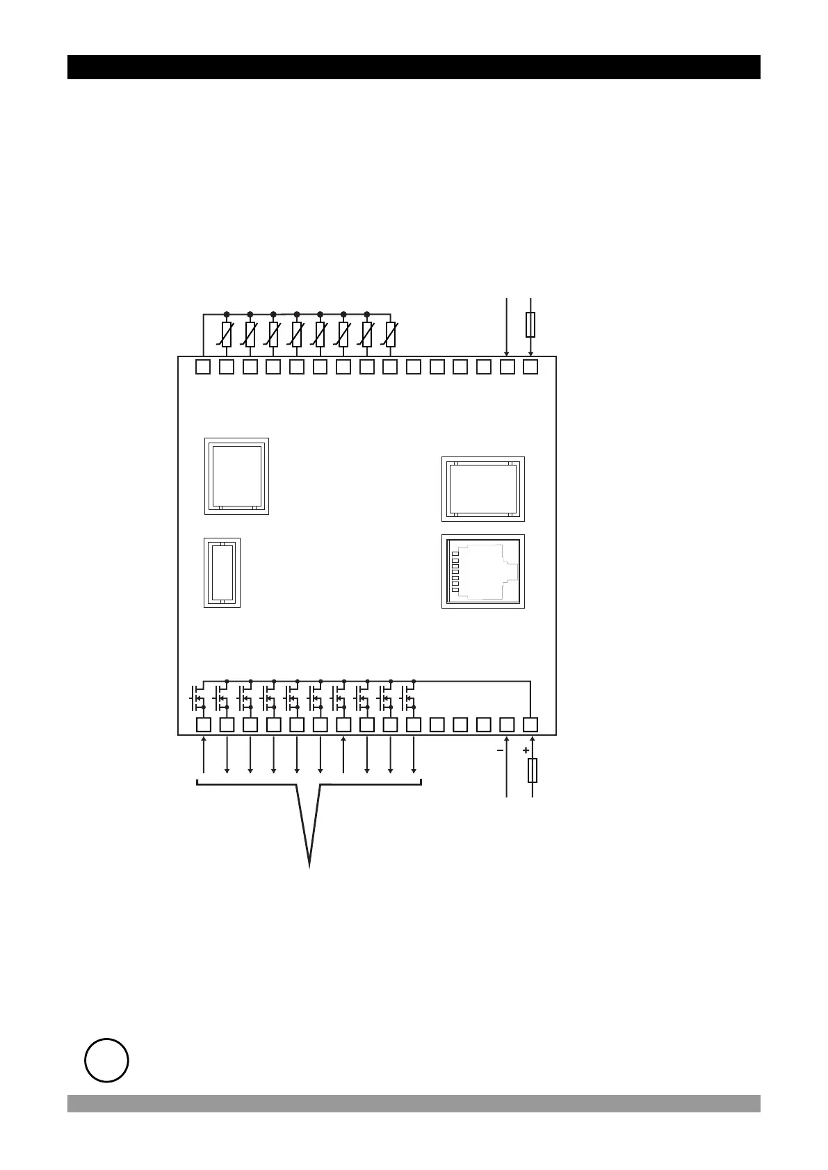
3.2.2 Device with Transistor Outputs
RS485, Ethernet and USB communications are optional
i
RS 232
COMMUNICATION
16
21 22
23
24
25 26
27
28 29
30
17
18 19
20
1 2
3
4
5
6
7
8 9
10
11 12
13
14
15
CH-1 ALARM
OUTPUT
CH-2 ALARM
OUTPUT
CH-3 ALARM
OUTPUT
CH-4 ALARM
OUTPUT
CH-5 ALARM
OUTPUT
CH-6 ALARM
OUTPUT
CH-7 ALARM
OUTPUT
CH-8 ALARM
OUTPUT
GENERAL ALR.
OUTPUT
GENERAL PRE- ALR.
OUTPUT
USB 2.0
COMMUNICATION
ETHERNET
OR
RS485
COMMUNICATION
Transistor Outputs
(Alarm Outputs for
Channels 1 to 8,
General Alarm Output and
General Pre-Alarm Output )
10 x 1A@24VZ
POWER
SUPPLY
24VZ ±%15
PT-100
CH-1
PT-100
PT-100
PT-100
PT-100
PT-100
PT-100
PT-100
CH-2CH-3CH-4CH-5CH-6CH-7CH-8
AGND
Process Inputs
(PT-100)
CH = CHANNEL
Power Supply Input
(It must be determined in order.)
100...240V V (- %15;+%10) 50/60Hz 7VA
24VV(-%15;+%10) 50/60Hz 7VA
24VZ(-%15;+%10) 7W
L
(+)
N
(-)

 Loading...