ü
Ýçindekiler
A visualinspectionofthisproductforpossibledamageoccuredduringshipmentis
recommendedbeforeinstallation.Itisyourresponsibilitytoensurethatqualifiedmechanical
andelectricaltechniciansinstallthisproduct.
Ifthereisdangerofseriousaccidentresultingfromafailureordefectinthisunit,poweroff
thesystemandseperatetheelectricalconnectionofthedevicefromthesystem.
Keepthepoweroffuntilallofthewiringiscompletedsothatelectricshockandtroublewith
theunitcanbeprevented.
Toreducetheeffectofelectricalnoiseondevice,Lowvoltageline(especiallysensorinput
cable)wiringmustbeseparatedfromhighcurrentandvoltageline.
Ifpossible,useshieldedcableandshieldmustbeconnectedtogroundonlyoneside.
Beforecommissioningthedevice,parametersmustbesetinaccordancewithdesireduse.
Incompleteorincorrectconfigurationcancausedangerousstiuations.
Before beginning installation of this product, please read the instruction
manual and warnings below carefully.
2.Installation
Ýçindekiler
2.1UnitConfiguration
Ýçindekiler
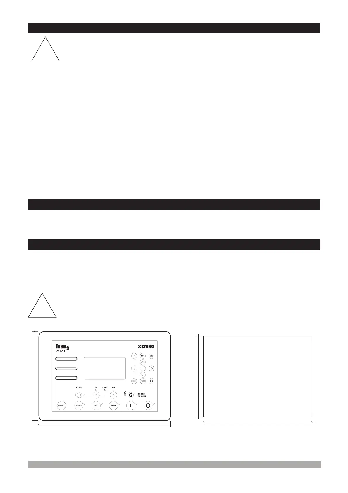
2.2PanelMounting
The unit is designed for panel mounting. Fixing is by two screw fixings.
Insert the unit in the panel cut-out from the front.
Insert the fixings in the slotted at the corners of the unit and tighten the fixing screws to secure
the unit against the panel.
1-
2-
During the equipment is putted in hole on the metal panel while mechanical
installation some metal burrs can cause injury on hands, you must be careful.
Figure 2.1 Front View Figure 2.2 Panel Cut-Out
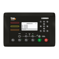
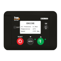
The unit can be programmed using the buttons and LCD display on the front panel or PC
Software.
2
182mm
135mm
152mm
229mm
!
!
 Loading...