2.3ElectricalConnection
3
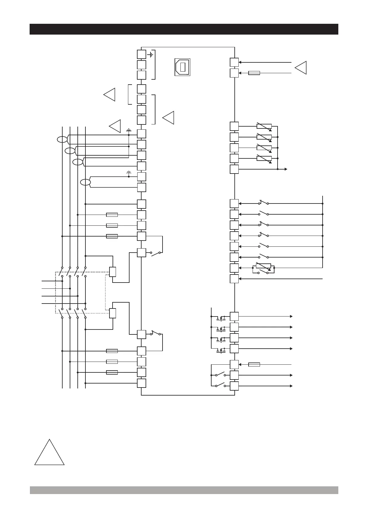
TRANS-AMF threephaseconnectionsschematic
1- Connecttheunitasshownintheappropriatediagram.Besuretoconnectthebattery
supplytherightwayroundandbatterynegativeshouldbegrounded.
2- TheCANinterfacerequiresthata120Ohmsterminatorisfittedtoeachendofthe
communicationslink. Thisterminationresistorisfittedinternallyintotheunit.Soitisnot
requiredexternally. ThescreenisgroundedatoneendONLY.
ScreenedcablemustbeusedforconnectingtheMagneticPickup,ensuringthatthe
screenisgroundedatoneendONLY.
i
3-
4-Currenttransformerssecondaryshouldbegrounded. TheCT of5VA srecommended.
!
25
LevelSenderor
Configurable AnalogInput-1
TemperatureSender
OilSender
24
23
35
21
22
BATTERY -
BATTERY +
40
42
41
5A
BATTERY +
27
26
Configurable AnalogInput-2
SenderCommon
18
19
17
H(+)
L(-)
J1939ECUs
34
33
BATTERY -
32
31
30
29
28
HighTemperatureor
ConfigurableInput-5
LowOilPressureor
ConfigurableInput-4
WaterLevelor
ConfigurableInput-3
ConfigurableInput-2
ConfigurableOutput-5
ConfigurableOutput-6
5A
ToEngine
Earth
USB
SCR
FUSE-7
FUSE-8
*
*
ITCANBEUSED
AS A DIGITAL INPUT
BY SELECTING
FROMTHEPROGRAM
PARAMETERS
*
*
*
3
1
ConfigurableOutput-3
39
38
37
36
ConfigurableOutput-4
TRANSISTOROUTPUTS
MAX.1 A
BATTERY +
20
-(SCR) +
MPU
2
EmergencyStopor
ConfigurableInput-1
ConfigurableInput-6
6
2
7
3
8
8A
8A
1
4
9
10
5
L1
GENERATOR
MAINS
L2
L3
N
M
LOAD
G
L1
L2
L3
N
Electricalinterlock
Mechanicalinterlock
11
12
13
14
15
16
Mains
Contactor
Relay
Generator
Contactor
Relay
FUSE 1-
FUSE 2-
FUSE 3-
FUSE-4
FUSE-5
FUSE-6
4
!
!
!
!
FuelOr
Output-1Configurable
CrankOr
Output-2Configurable
D+(W.L.)
Charge Alt.
Max.300VV
Max.300VV
CabinTemperatureor
ConfigurableInput-7
FUSE FUSE FUSE-5, FUSE-6 FUSE-3, FUSE-4 8A. T
FUSE-7 6A. T
FUSE-8 Max. 10A. T
-1, -2, 2A. T
44
45
43
A(+)
B(-)
RS-485
(Optional)
 Loading...