Do you have a question about the EMKO EAOM-19 and is the answer not in the manual?
Details the EAOM-19's automatic transfer function, monitored parameters, and controlled functions.
Illustrates terminal layout, pin assignments, and general connection guidelines.
Presents wiring schematics for single and three-phase AC power systems.
Details pin functions, recommended cable sizes, and connection notes.
Provides a functional explanation for each pin connection on the unit.
Guides on accessing and modifying operator and technician parameters.
A comprehensive list of all configurable parameters, their definitions, units, and ranges.
Details the meaning of all failure LEDs, including start failure, temperature, and voltage issues.
Explains the automatic sequence for mains failure and restoration.
| Brand | EMKO |
|---|---|
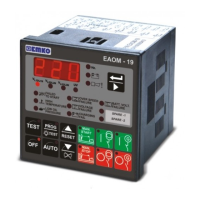
| Model | EAOM-19 |
| Category | Control Unit |
| Language | English |