15
MAINS
MAINSCONTACTOR GENERATORCONTACTOR
LOAD
GENERATOR
GENERATORRELAY
MAINSRELAY
FUSE-6
FUSE-5
FUSE-4
FUSE-3
1512
L1 L1
L1
N N
N
L2 L2
L2
L3 L3
L3
14 13 18 17 1619
CHARGE
GEN.
D+(W.L.)
B+
CHARGEGENERATOR
FUSE-2
40 A
40 A
FUSE-1
BATTERY
+
-BAT
+BAT
+BAT
STARTER
BATTERY NEGATIVEMUSTBEGROUNDED
START
RELAY
SOLENOID
RELAY
LOWOIL PRESSURE
HIGHTEMPERATURE
CONFIGURABLEINPUT1
CONFIGURABLEINPUT2
HORNOUTPUT
1 2 3 4 5 7891011 6
1
2
1
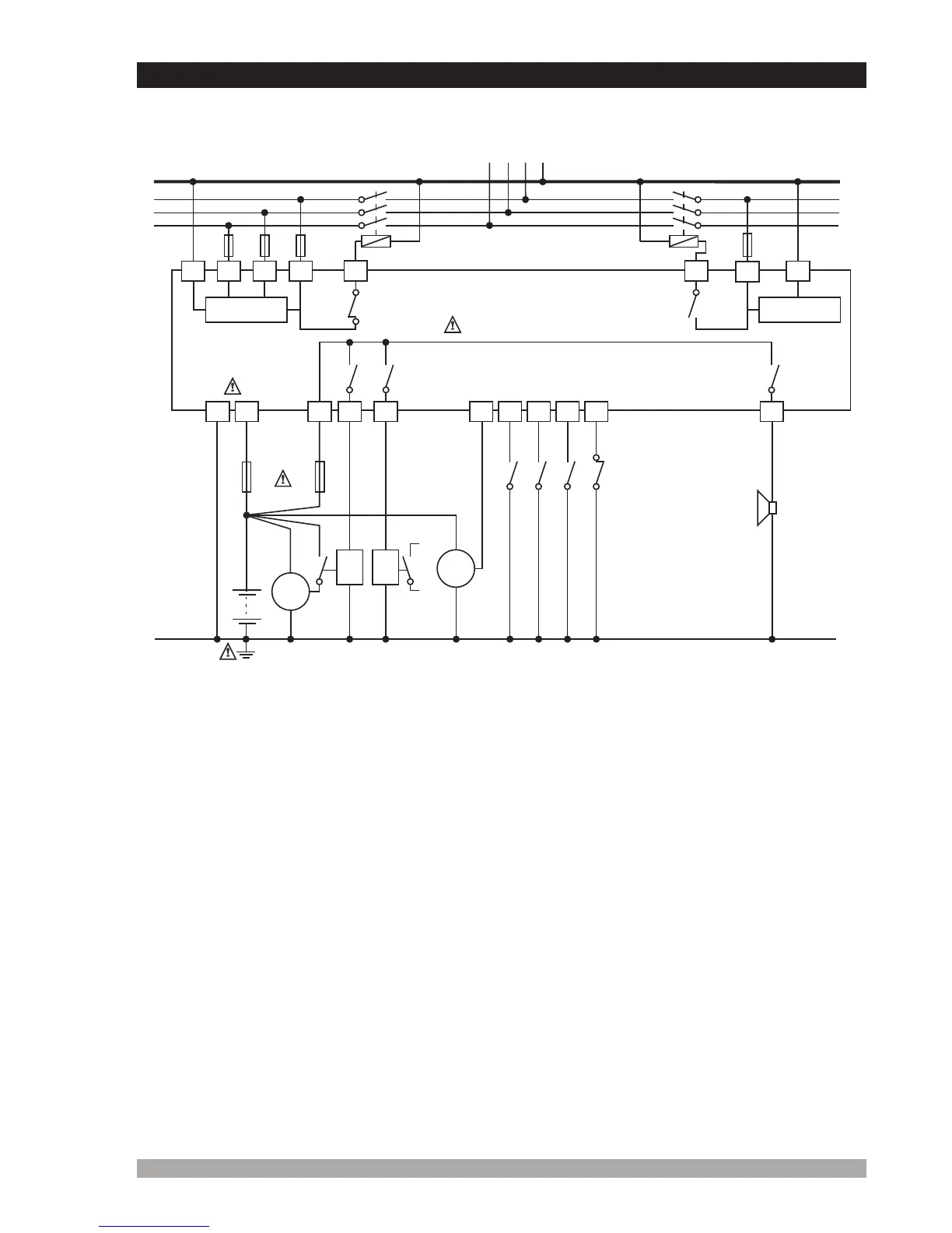
3.2.2EAOM-19ThreePhaseConnectionsSchematicForTN-C ACPowerSystems
Connecttheunitasshownintheappropriatediagram,Section3.2.1or3.2.2.
Ensurethebatterysupplyisofthecorrectpolarity,andthatthebattery
negativerailisgrounded.Theconnectorscanbeunpluggedfromtherearof
theunitforconvenienceandtospeedupinstallation.
c
Thefusesshouldbeasfollows:
FUSE1 1A.T
FUSE2 Accordingtocurrentrequiredbysolenoidsetc.
FUSES3,4 Max.5A.
FUSES5,6 1A.
c
1-
2-
MEASUREMENT
CIRCUIT
MEASUREMENT
CIRCUIT
Symbol means Vac,
Symbol means Vdc
V
Z
5A@250VV
5A@250VV
16A@32VZ 16A@32VZ
16A@32VZ
3
c
3-