17
Table3.1showstheconnectionsandrecommendedcablesizes. Table3.2describes
thefunctionsoftheconnections.
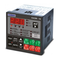
+BatterysupplytoEAOM-19
2
1.0
Suppliestounit
-BatterysupplytoEAOM-19
1
1.0
Suppliestounit
Pin
Description
CableSize
(mm²)
Notes
3
+Batterysupplyinput
2.5
SuppliestoPin
4,5,6.
Outputtostartrelay
4
2.5
16 A.Max
+DCsupplayfrom
PIN3
OutputtoFuel/StopSolenoid
5
2.5
Outputtohorn
6
2.5
Inputfromoilpressureswitch
7
1.0
Switchto"0"Volt
Inputfromtemperatureswitch
8
1.0
Switchto"0"Volt
Configurablefailureinput-1
9
1.0
Switchto"0"Volt
Configurablefailureinput-2
10
1.0
Switchto"0"Volt
Inputfromchargegenerator
11
1.0
Mainsvoltageneutral
12
1.0
Mainsvoltageinput(L1)
13
1.0
Mainsvoltageinput(L2)
14
1.0
3phaseonly
Mainsvoltageinput(L3)
15
1.0
3phaseonly
Generatorvoltageneutral
16
1.0
Generatorvoltageinput(L1)
17
1.0
Mainscontactor
18
2.5
Relayoutput(5A)
Generatorcontactor
19
2.5
Relayoutput(5A)
16 A.Max
+DCsupplayfrom
PIN3
16 A.Max
+DCsupplayfrom
PIN3
3.4UnitWiring
Table3.1UnitWiring