18
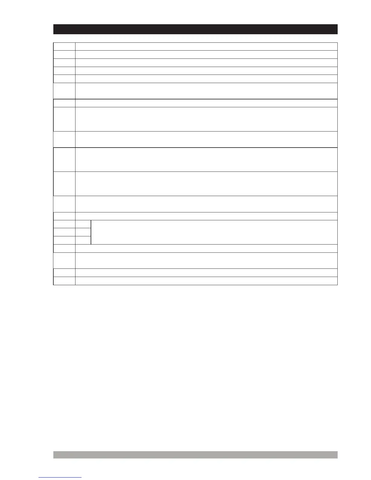
Table3.2UnitWiringDescription
Pin
Function
1
NegativebatteryinputsuppliesEAOM-19.
2
PositivebatteryinputsuppliesEAOM-19.
3
Batterypositiveinput.SuppliesPin4,5and6.
4
OutputtoStartrelay.+DCsupplyfrompin3.Controlsstartermotor.
6
Outputtohorn.+DCsuppliesfrompin3.(Configurable)
12
Mainsvoltageneutral.
16
Generatorvoltageneutral.
18
Mainscontactor. (NC).Relayoutput
19
Generatorcontactor. (NO).Relayoutput
5
OutputtoFuel/Stopsolenoid.+DCsupplyfrompin3.Controlsfueltoengineor
controlsenginestopping
8
Inputfrom Temperatureswitch.Switchedto0V,whenenginetemperatureexceeds
thermostatsetting.
11
Inputfromchargegenerator.Canbeusedtodetectwhenenginehasstarted.Mustbe
connectedto+BAT ifnotused.
17
InputfromgeneratorL1phase.Unitcanbeprogrammedtousefrequencyof
alternatoroutputtodetectwhenenginehasstarted.
7
InputfromOilPressureswitch. Theoilpressureswitchmustbethetypethatopens
whenoilpressureisnormal,andclosesonlowoilpressure.(failureconditionor
enginestopped.)
9
Configurableinput-1.Normallyopen.Whenswitchedto0V,soundsthehornand
flashesSPARE-1LEDonpanel.Canbeprogrammedtostoptheengine,de-
energisethegeneratorcontactor .ortheremoteinhibit
10
Configurableinput-2.Normallyopen.Whenswitchedto0V,soundsthehornand
flashesSPARE-2LEDonpanel.Canbeprogrammedtostoptheengine.de-
energisethegeneratorcontactor .ortheremoteinhibit
13
14
15
L1
L2
L3
Mainsvoltageinputs.Usedtodetectfailureforcontrollingautomatictransferof
loadtogenerator.Pins14and15notusedonsinglephaseapplications.
3.5UnitWiringDescription