3
Unless explicitly specied otherwise, the precision is specied in the range
from 8 % to 100 %.
The precision specications have this formula
±([% appliance data]+[quantity of the lowest valid numbers])
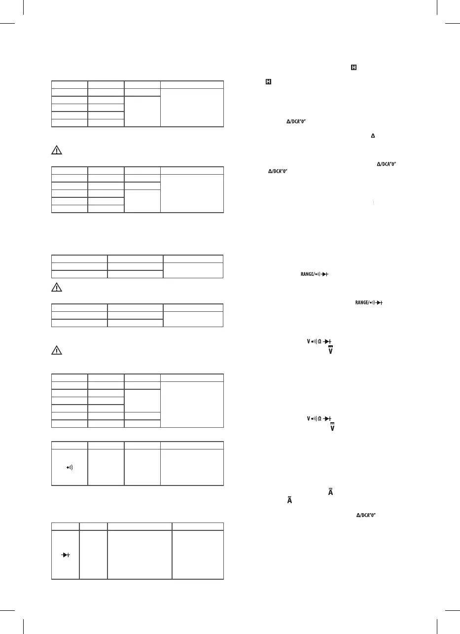
Direct current (DC)
Range Resolution Precision Overload protection
400.0 mV 0.1 mV ± (0.8% + 5)
600 V ef.
4.000 V 1 mV
± (2.0% + 5)
40.00 V 10 mV
400.0 V 100 mV
600 V 1 V
Input impedance: range 400 mV: > 100 M
Other ranges: 10 M
Max. allowed input voltage: 600 V DC
Alternating current (AC)
Range Resolution Precision Overload protection
400.0 mV 0.1 mV ± (2.0% + 5)
600 V ef.
4.000 V 1 mV ± (1.2% + 5)
40.00 V 10 mV
± (1.5% + 5)400.0 V 100 mV
600 V 1 V
Input impedance: 10 M
Frequency range: 40–400 Hz
Max. allowed input voltage: 600V ef.
Response: average, calibrated at the eective value of the sinus progress
Direct current (DC)
Range Resolution Precision
400 A 0.1 A
± (2.5% + 5)
600 A 1 A
Max. allowed input current: 600 A
Alternating current (AC)
Range Resolution Precision
400 A 0.1 A
± (2.5% + 5)
600 A 1 A
Frequency range: 50–60 Hz
Do not use the current sensor above its rated max. frequency 60 Hz.
Max. allowed input current: 600 A
Response: average, calibrated at the eective value of the sinus progress.
Resistance
Range Resolution Precision Overload protection
400.0 100 m ± (1.2% + 7)
600 V ef.
4.000 k 1
± (1.0% + 5)40.00 k 10
400.0 k 100
4.000 M 1 k ± (1.2% + 5)
40.00 M 10 k ± (1.5% + 7)
Circuit connection test
Range Resolution Precision Overload protection
0.1
If the resistan-
ce is lower
than ca 30 ,
the buzzer
will sound
600 V ef.
Note:
When the resistance is between 30 and 150 , the buzzer may sound or
it may not. When the resistance is above 150 , the buzzer will not sound.
Diode test
Range Resolution Description Overload protection
1 mV
Displays an approximate
decrease of voltage in the
permeable direction of the
diode. Voltage in an open
circuit: Approximately 2.0 V
Test current: Approximately
0.6 mA
600V ef.
Measured data hold mode
When you push the HOLD button, you can keep the measured values on
the display.
As an indicator, the display will show the symbol .
If you want to terminate this mode, just push this button again.
The symbol will disappear.
Using the relative mode
When you choose the relative mode, the measurement appliance will store
the present measured values as a reference to compare with subsequent
measurements and then it will clear the display.
1. Push the button “ . The measurement appliance switches to the
relative mode and stores the present measurement values for future
reference and the display shows an indicative symbol .
2. The display shows zero. When you take a new measurement, the display
shows the dierence between the reference value and the newly meas-
ured value.
3. If you wish to quit the relative mode, push the button “ again.
The icon “ disappears.
Note:
1. For measurements, which have an automated range and manual range,
the measurement appliance automatically switches to manual range, if
you choose the relative mode. Before choosing the relative mode, set the
desired manual range.
2. When using the relative mode, the present value of the tested item must
not exceed the full range value you selected. If necessary, increase the
range.
Manual and automated range setting
For measurement functions, which have the automated range and manual
range mode, the default mode of the measurement appliance is the auto
-
mated mode. In the automated range mode the measurement appliance has
the text “Auto” on its display.
1. By pushing the button “ “ you enter the manual range mode.
The “Auto” symbol disappears.
2. By each pushing the button you increase the range. After reaching the
peak fo the range, the measurement appliance returns to the lowest range.
3. To terminate the manual range mode, push the “ “ button and
hold it longer than 1 second. The measurement appliance will return to
the automated range mode and will show the “Auto” symbol again.
Measuring the direct current (DC) voltage
1. Connect the black test conductor to the terminal “COM“ andthe red test
conductor to the terminal .
2. Se the rotary switch to the position
.
3. Connect the test conductors to the measured source or circuit. The
measured value will be shown on the display. Also the polarity of the
connected red test conductor will be displayed.
Note:
To prevent the risk of an electric shock or damage to the appliance, do not
attach the terminals to voltage higher than 600 V.
Measuring the alternating current (AC) voltage
1. Connect the black test conductor the terminal “COM“ and the red test
conductor to the terminal .
2. Set the rotary switch to the position
.
3. Connect the test conductors to the measured source or circuit. The
measured value will be shown on the display.
Note:
To prevent the risk of an electric shock or damage to the appliance, do not
attach the terminals to voltage higher than 600 V.
Measurement of direct current (DC) or alternating
current (AC)
1. Set the rotary switch to the position for measurement of direct current
or to the position
for the measurement of alternating current.
2. If the display does not show zero, when the measurement appliance is in
the direct current measurement mode, push the button to reset.
3. Push the lever to grab the measured conductor into the clamps. Check
that all the lamps hold tight.
Note:
a. Only one conductor can be clamped at the same time.
b. To get precise readings, the conductor must be in the middle of the
clamps.
c. Do not touch any conductor with your hand or skin.
4. The measured value will be shown on display.
 Loading...