Emotron AB 01-3990-11r3 Kabelaansluitingen 135
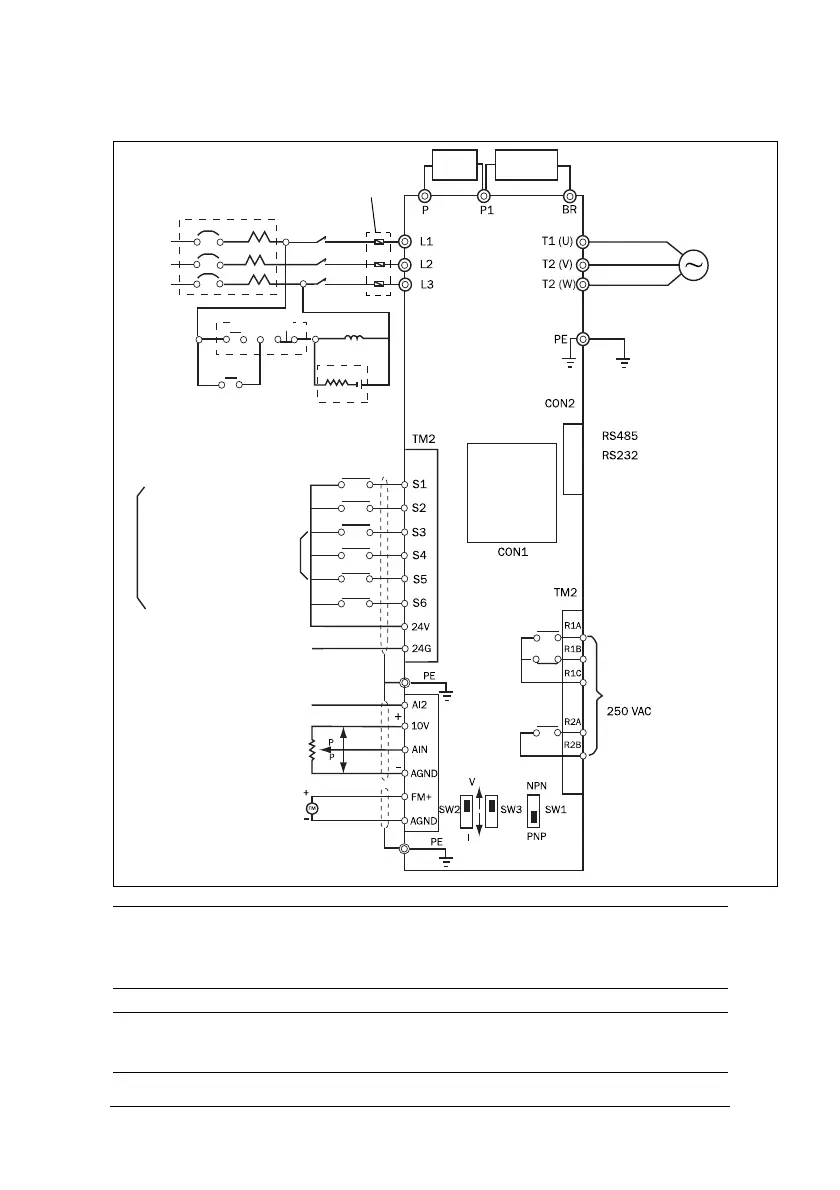
Bedradingsschema voor VSC-serie
LET OP: Raadpleeg de beschrijving van de aansluitklemmen van het hoofd-
circuit (P1,BR) en de specificatie van de remweerstand om de waarde te
kiezen.
LET OP: Het bovenstaande schema heeft alleen betrekking op het model
met 440 V: 4-7,5 kW.
Gelijkstro-
spoel
Rem-
weerstand
Inductiemotor
400 V: speciale aarding
Digitaal
bedien-
paneel
Vermogensautomaat
Wissel-
Stroom-
bron
RC-Blusfilter
Multifunctionele
Rechtsom/stop of start/stop
Linksom/stop of linksom/
Toerentalregeling
Multifunctionele ingangsklem
Massapunt voor PNP-ingang
Massapunt voor NPN
Reset/foutherstel
Frequentie-instelling
Frequentie-indicator
0-10 V DC
Stroom-
uitgang
stroom-
ingang
2-10 V/4-20 mA (na versie 2.3)
I-stand: 0-20mA-signaal
V-stand: 0-10V-signaal
SW1: NPN/PNP selectief
(opmerking 1)
(opmerking 2) (opmerking 2) (opmerking 2)
(optiekaart)
Geheugenkaart
rechtsom
omsmoor-
uitgangsklemmen
Magneeet-
(MC)
AAN/UIT
(multifunctionele ingangsklem)
multifunctionele ingangsklem
SW2: AIN 0~10 V/0~20 mA selectief
SW3: AI2 0~10 V/0~20 mA selectief of
schakelaar
Monteer
snelwerkend
 Loading...