Emotron AB 01-3990-11r3 Wiring notes 51
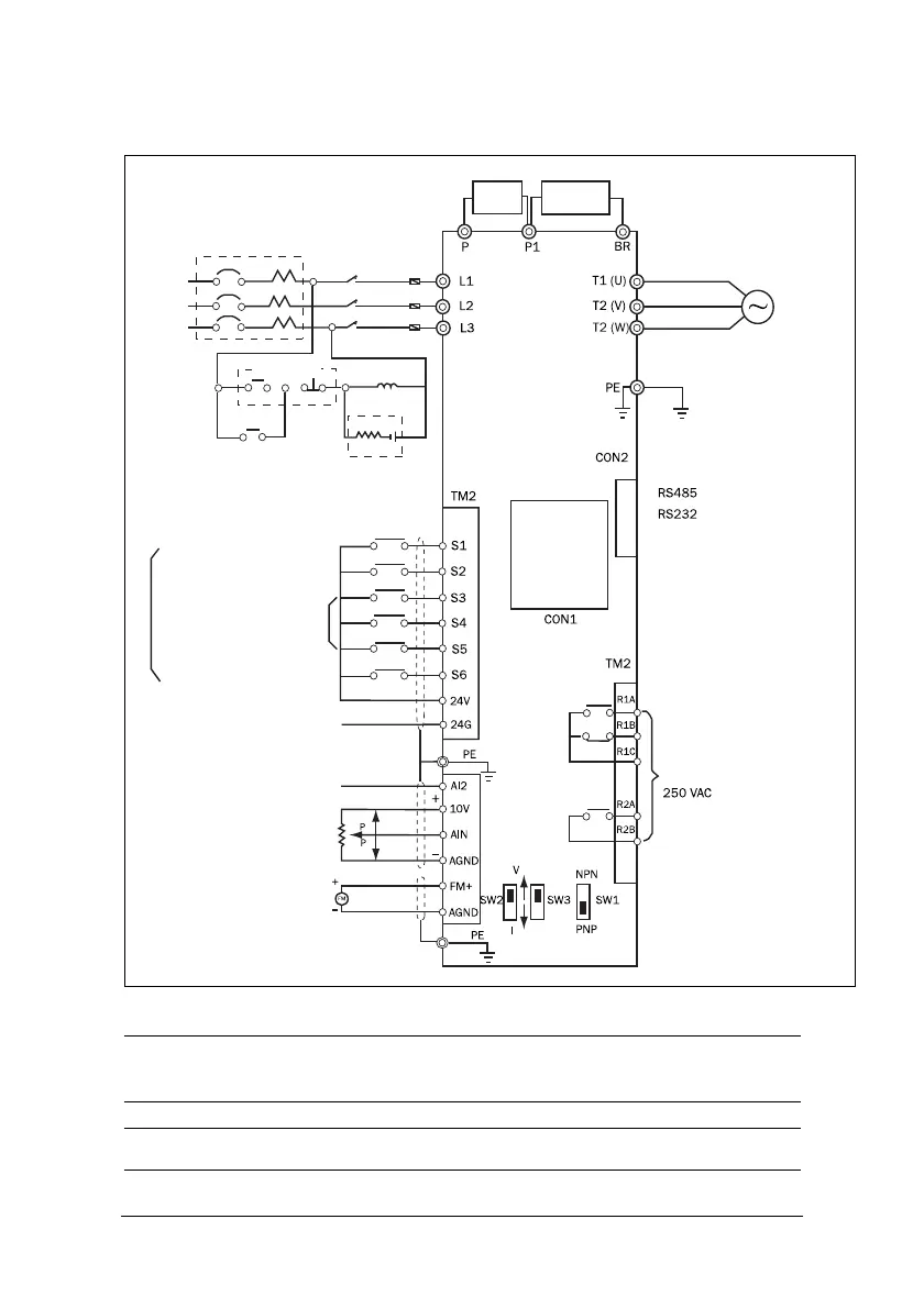
Wiring diagram for VSC series
NOTE: Please refer to description of main circuit terminals (P1,BR) and
specification of braking resistor for value selection.
NOTE: The diagram above refers to 440V: 4 to 7.5 kW only.
DC
reactor
Braking
Resistor
Induction motor
400 V: Special ground
Digital
Control
panel
Moulded-case circuit breaker
AC
Power
source
Burst absorber
Multifunctional output terminals
forward/stop or run/stop
Reverse/stop or reverse/
Speed control
Multifunction input terminals
Common point for PNP input
Common point for NPN
Fault reset
Multifunction input terminal
Frequency setting device
Frequency indicator
0~10VDC
Power
output
Power
input
(note 1)
(Note2) (Note2) (Note2)
(Option card)
Memory card
forward
Magnetic
contactor
(MC)
Use
fast
acting
SW 2: AIN 0~10V/0~20mA selective
SW 3: AI2 0~10V/0~20mA selective
or 2~10V/4~20mA
I position: 0~20mA signal
V position: 0~10V signal
SW1: NPN/PNP selective
(Multifunction input terminal)
ON/OFF
fuses
 Loading...