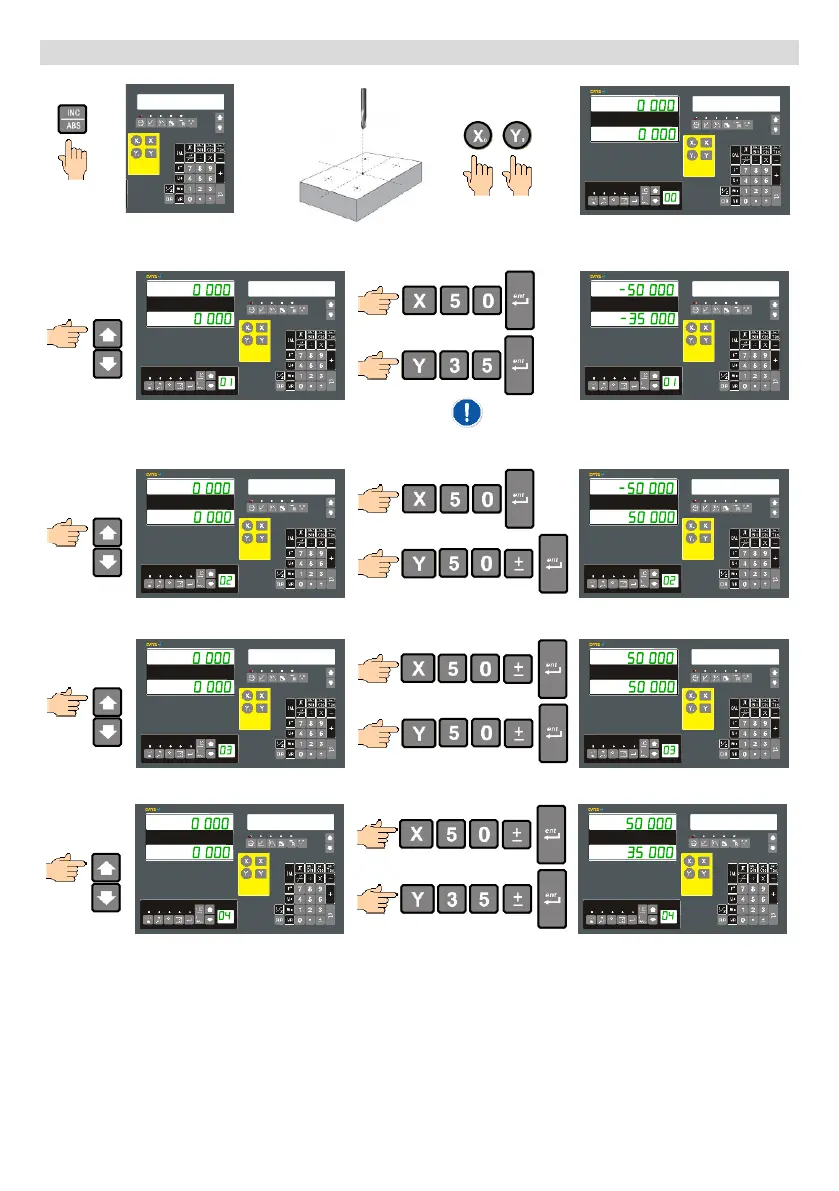
Define a SDM pattern: (Direct Entry method)
ABS
Enter ABS mode, move to desired workpiece datum and set this as the datum by zeroing the axes.
SDM MODE
SDM MODE
Select SDM #1, and enter the desired co-ordinate.
SDM MODE
SDM MODE
Select SDM #2, and enter the desired co-ordinate.
SDM MODE
SDM MODE
Select SDM #3, and enter the desired co-ordinate.
SDM MODE
SDM MODE
Once all the points have been entered you can now start using them straight away. As long as the Message window
is displaying the text “SDM MODE”, the axis displays are showing the current position of the tool from the SDM co-
ordinate as displayed in the SDM window.
This direct entry of SDM co-ordinates is particularly useful when working on batch jobs or where centre or origin
co-ordinates of features, to be machined, can be read from drawings.
The displayed value after pressing [enter] will be of
opposite sign. This is because we are working-to-zero
relative to the ABS datum and we are currently at 0, 0.
- 19 -
 Loading...