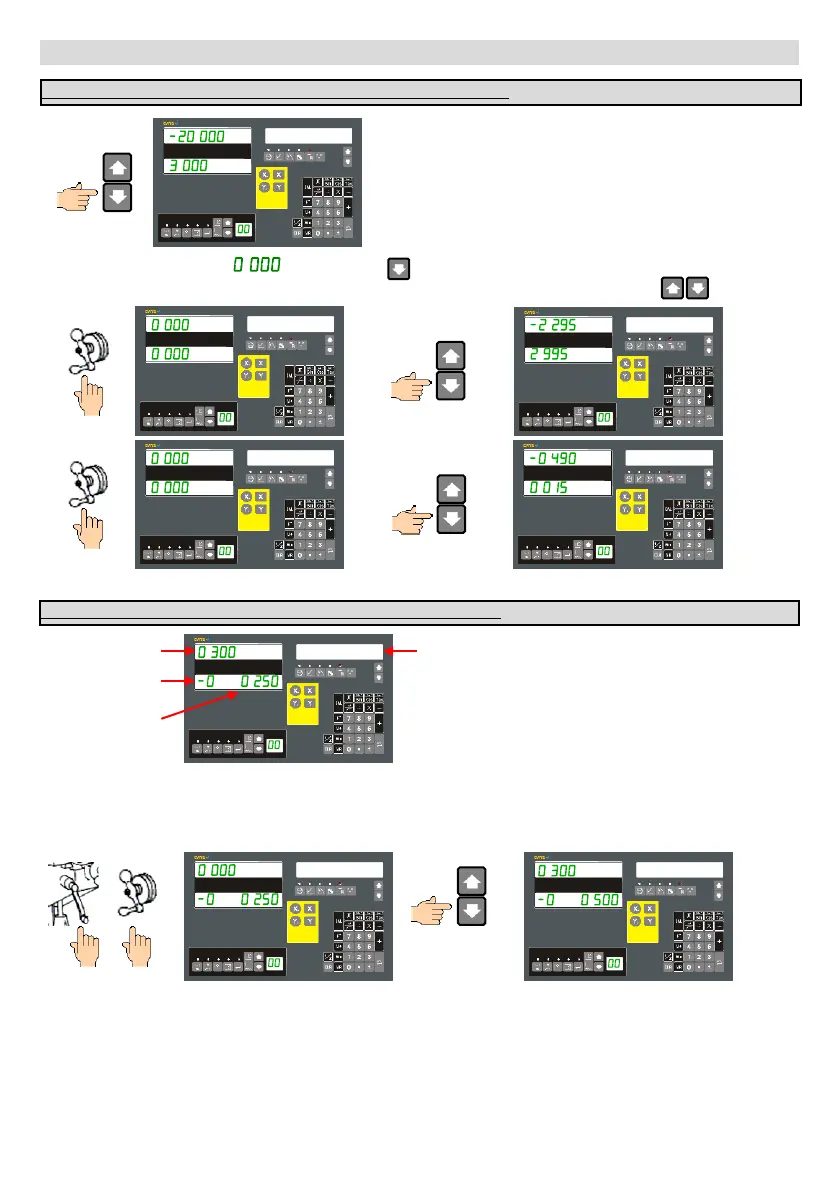
The message window will show the first machining Point
with the X & Y-axis displays left aligned to indicate that it
is operating in a special mode.
PT 1
Move the X-axis and Y-axis to . . Then press the key to move to the next next point and repeat the process
until the ARC machining operation is completed. You can navigate through the points using the keys
PT 1
PT 2
PT 2
PT 3
Repeat as required…
The following is only required for the XY Plane. (2-axis and 3-axis DRO)
The DRO will simulate a Z-axis position
based on the DIAL INC and Z DIAL
values configured in Setup. It is the
operators responsibility to move the
dials as per the DRO display.
Z-
0.500
Z-
0.250
Move X-axis to zero and then move the Z-axis. When you have moved the Z-axis use the message navigation keys to
inform the DRO that the movement has been completed, and move to the next point. This process can be repeated
until the inclined machining operation is completed.
The following is the operating mode on XZ & ZY Plane on 2-axes DRO.
X-axis value
Z-axis rotations
Z-axis simulated
dial reading
Z-axis simulated
DRO reading
Z-
0.250
Repeat as required…
Enhanced Radius Function (Auto-R): Continued…
- 36 -
 Loading...