Do you have a question about the ENC EDS800 Series and is the answer not in the manual?
Covers warnings, safe operations, and potential hazards.
Specifies suitability for three-phase AC asynchronous motors in industrial fields.
Details operational characteristics, low-speed running, and load considerations.
Provides guidelines for safe disposal of the inverter and its components.
Instructions for checking the inverter for damage and verifying contents upon receipt.
Explains the coding system for inverter models and their specifications.
Details how to read and understand the information on the inverter's nameplate.
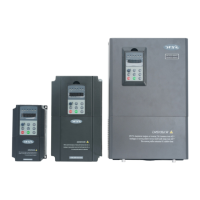
Lists different inverter series types with their power, current, and motor ratings.
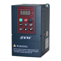
Identifies the external parts and components of the EDS800 inverter.
Provides dimensional drawings and weight information for the inverter.
Shows detailed dimensions of the keypad and its enclosure.
Lists technical specifications, input/output ratings, and operational parameters.
Specifies environmental conditions and location requirements for inverter installation.
Guides on how to safely remove and install specific parts like the keypad.
Crucial safety and procedural notes to follow before and during wiring.
Details the connections for the main power input and output terminals.
Illustrates the fundamental wiring connections for basic inverter operation.
Explains wiring for control signals, terminals, and jump wires.
Covers the basic operation, modes, and states of the inverter during running.
Explains the layout, functions, and operation of the inverter's control keypad.
Provides steps for checking and performing the initial power-up of the inverter.
Defines symbols used in the parameter schedule for clarity.
Presents a graphical overview of the inverter's function parameters.
Details parameters related to the fundamental operation of the inverter.
Explains parameters controlling the inverter's start, stop, and braking functions.
Describes parameters for auxiliary operational modes and functions.
Covers parameters specific to closed-loop control operation.
Details parameters for the inverter's integrated PLC functionality.
Explains parameters related to terminal inputs and outputs.
Describes parameters for specific traverse or motion control functions.
Details parameters related to frequency setting and control methods.
Explains parameters for motor control, including vector control.
Lists parameters for various protection mechanisms to safeguard the inverter.
Describes parameters for logging and retrieving fault records.
Covers parameters related to device identification and manufacturer settings.
Provides solutions and remedies for common inverter failures.
Explains how to access and interpret recorded fault history.
Details the procedure for clearing fault codes and resetting the inverter.
Outlines regular maintenance tasks to ensure optimal performance.
Guides on inspecting and replacing components prone to wear or damage.
Information regarding warranty and repair services for the inverter.
Provides instructions for storing the inverter properly.
Illustrates typical scenarios of speed regulation using the inverter.
Shows examples of operating the inverter via terminal inputs.
Demonstrates examples of multi-step speed control configurations.
Presents examples of setting up and running closed-loop control systems.
Illustrates examples of consecutive or sequential operational modes.
| Series | EDS800 |
|---|---|
| Cooling Method | Forced air cooling |
| Enclosure Rating | IP20 |
| Control Mode | V/F control |
| Overload Capacity | 150% rated current 60s; 180% rated current 10s |
| Communication | RS485 |
| Protection Features | Over-current, over-voltage, under-voltage, over-heat, overload, short circuit |
| Efficiency | 98% |
| Operating Temperature | -10°C to +50°C |
| Storage Temperature | -20~60℃ |
| Humidity | 5-95% (non-condensing) |