S
Sharon BrennanSep 10, 2025
What to do if the Endress+Hauser Transmitter calibration is aborted?
- RRichard WilliamsSep 12, 2025
If the calibration of your Endress+Hauser Transmitter is aborted, repeat the calibration process.

What to do if the Endress+Hauser Transmitter calibration is aborted?
If the calibration of your Endress+Hauser Transmitter is aborted, repeat the calibration process.
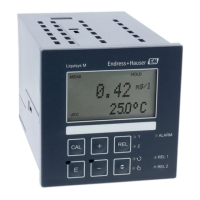
What to do if the Endress+Hauser Liquisys M CUM223 current output 1 range is too small?
If the current output 1 range on your Endress+Hauser Transmitter is too small, decrease the current output spreading.
| Manufacturer | Endress+Hauser |
|---|---|
| Product Name | Liquisys M CUM223 |
| Category | Transmitter |
| Ambient Temperature | -20 to 60 °C (-4 to 140 °F) |
| Measured variable | Conductivity |
| Accuracy | ±0.5% of measured value ±0.5 μS/cm |
| Temperature Compensation | Automatic |
| Output Signal | 4-20 mA |
| Communication Protocol | HART |
| Power Supply | 24 V DC |
| Display | LCD |
| Protection | IP65 |
Personnel qualifications for installation, operation, and maintenance.
Intended applications for the transmitter.
Safety conditions and electromagnetic compatibility.
Precautions for safe operation and handling of faulty products.
Product design meets state-of-the-art safety requirements.
Explains common electrical symbols used in the manual.
Steps to verify the condition and completeness of the received product.
Lists the items included in the delivery for field and panel instruments.
Locating order code and serial number on the nameplate.
CE mark and CSA general purpose approval information.
Step-by-step guide for complete measuring point installation.
Components of a complete measuring system.
Environmental and spatial requirements for instrument installation.
Installation specifications for the field instrument housing.
Installation specifications for the panel-mounted instrument.
Methods for mounting the field instrument (wall, post).
Securing the panel-mounted instrument.
Checks to perform after installation is complete.
General guidelines and notices for wiring the device.
Detailed wiring diagram for the transmitter.
Steps to connect the field instrument.
How to connect the measuring cable and sensor.
Checks after electrical connections are made.
Overview of methods for operating the transmitter.
Description of display and physical controls.
Explanation of LED display indicators.
Description of the LC display and physical keys.
Detailed explanation of each key's function and assignments.
Explanation of AUTO, Escape, Locking, and Unlocking key functions.
How to switch between automatic and manual operating modes.
How to switch between automatic and manual operating modes.
Overview of the device's operating modes and access codes.
Fixed device access codes for setup and calibration.
How menu functions and groups are organized.
Freezing of output values during setup or calibration.
Pre-operation checks for correct installation and voltage.
Initial steps after powering up the transmitter.
Default configuration values for various functions.
Step-by-step configuration for essential measurement settings.
Main section for configuring system parameters.
Configuration of operating mode and sensor settings.
Configuration of temperature and wiper settings.
Using current input for monitoring and feedforward control.
Using current input to monitor flow for alarms and dosing.
Applying flow rate as feedforward control to PID controller.
Configuring individual current outputs and characteristics.
Defining alarms and configuring output contacts.
Selecting monitoring functions for sensor and process checks.
Monitoring for upper/lower limits and triggering alarms.
Monitoring controller activity and switch-on/off periods.
Monitoring for signal changes and deviations.
Selecting and configuring relay contacts for functions.
Assigning relay contacts to turbidity and temperature limit values.
Defining controller types (P, PI, PD, PID) and their parameters.
Setting a constant dosage value.
Combining PID control with a minimum basic load.
Optimizing control parameters (Tn, Kp) using a recorder.
Types of signal outputs (pulse length, pulse frequency).
Outputting controller actuating variable via current output 2.
Selecting between maximum and minimum function characteristics.
Simple cleaning option with time intervals.
Advanced cleaning with variable intervals and post rinse times.
Main section for configuring relay functions.
Selecting which relay contact to configure.
Setting limit contactors for turbidity.
Setting limit contactors for temperature.
Configuring PID controller parameters.
Setting up the timer for cleaning.
Setting up the Chemoclean cleaning function.
Entering and configuring concentration measurement curves.
Accessing service functions like language and code entry.
Information on device version and module details.
Communication settings for HART or PROFIBUS.
Referencing HART/PROFIBUS operating instructions.
Procedures for calibrating the measuring chain.
Performing calibration using three samples.
Entering laboratory determined correct values.
Entering corrections if sample values were determined in lab.
Compensating for backscatter from sensor environment.
Adjusting conversion factor or slope values.
Displaying calibration points, slope, and conversion factor.
Default settings for residual concrete water applications.
Main section for calibration procedures.
Selecting calibration type (3-Pt, Corr, Edit, Refl, 1-Pt, Data).
Entering concentration for the first calibration sample.
Entering concentration for the second calibration sample.
Entering concentration for the third calibration sample.
Selecting calibration type for data set 2.
Selecting calibration type for data set 3.
Entering concentration for the first calibration sample.
Entering concentration for the second calibration sample.
Entering concentration for the third calibration sample.
Selecting calibration type for data set 4.
Entering measured value for clear media calibration.
Selecting one-point calibration.
Selecting calibration data.
Displaying the slope of sensor characteristic 1.
Displaying the slope of sensor characteristic 2.
Displaying the conversion factor.
Calibrating measurement to a reference value by linear shift.
Proportional adaptation of measured values to a reference value.
General guidance for diagnosing and resolving issues.
Table of system errors, causes, and remedial measures.
Table of errors related to the process and their solutions.
Table of errors related to the instrument itself and their solutions.
General maintenance tasks for the measuring point.
Procedures for cleaning the transmitter housing.
Steps to test the operability of the measuring point.
Instructions for replacing the turbidity sensor.
Information on maintaining the assembly.
Step-by-step guide for disassembling the panel-mounted instrument.
Step-by-step guide for disassembling the field instrument.
Procedure for replacing the central module and data entry.
Procedures for returning devices for repair or calibration.
Guidelines for environmentally sound disposal of the device.
Information on turbidity sensors CUS31 and CUS41.
Details on cables and junction boxes for connections.
Weather protection covers and posts for mounting.
Compact turbidity measuring station CUE31.
Available optional software and hardware packages.
Specifications for measured variables, ranges, and inputs.
Specifications for output signals, load, and contact outputs.
Details on supply voltage and fieldbus connections.
Resolution, error margins, and repeatability.
Ambient, storage, and operating environmental conditions.
Dimensions, weight, material, and terminal specifications.
Visual representation of function group configurations.