Battery charger BC1 English
D01001-02 15
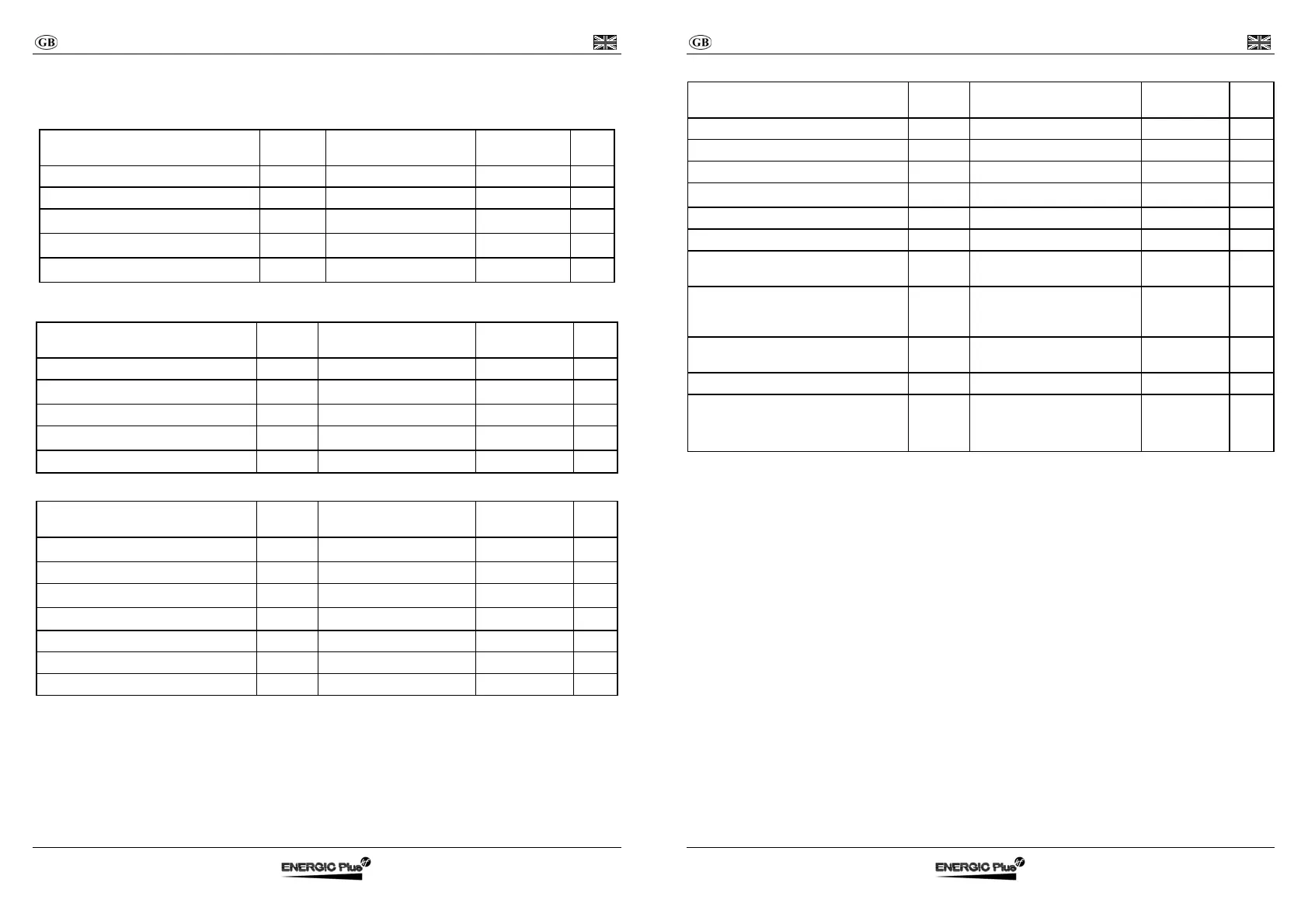
TECHNICAL FEATURES
Ta=25°C unless otherwise specified.
Mains side
Description Symbol Test Condition
Value and/or
Range
Unit
Supply Voltage Vin - 230 ± 10% Veff
Frequency f - 50 ÷ 60 Hz
Absorbed Maximum Current
Iin
max
P = P
max
5 Aeff
Power Factor
cosϕ
P = P
max
0,7 -
Absorbed Maximum Power
Pin
max
P = P
max
850 W
Battery side
Description Symbol Test Condition
Value and/or
Range
Unit
Output current ripple - I = I1 < 5% -
Absorbed current
I
a
Equipment turned off < 1 mA
Output voltage ripple - U = U1 < 1% -
Maximum power supplied
P
max
U = U1, I = I1 720 W
Output capacity C - 1000
μF
General
Description Symbol Test Condition
Value and/or
Range
Unit
Operating range of temperature
ΔT
- from -20 to +50 °C
Maximum relative humidity RH - 90% -
Switching frequency
f
c
- 80 ± 5% kHz
Efficiency
η
At each condition > 85% -
Maximum size a×b×c Without connecting cable 285×105×75 mm
Weight - Without connecting cable 1390 g
Enclosure class - - IP20 -
Battery charger BC1 English
D01001-02 16
Protection and Safety
Description Symbol Test Condition
Value and/or
Range
Unit
Insulation - Mains to Battery side 1250 V
AC
Insulation - Mains side to Earth 500 V
DC
Insulation - Battery side to Earth 500 V
DC
Leakage current
I
L
Supplied equipment < 3 mA
Input fuse F1 Inside the equipment 10 (delayed) A
Output fuse F2 Inside the equipment 40 A
Minimum output voltage of operation
(Battery Detector)
- Equipment turn on 1,3 V/cell
Reverse output polarity - At the connection to the
Battery
Protection
provided by
fuse F2
-
Thermal protection of semiconductors
(Temperature of Thermal Alarm)
- Ta=55°C 100 °C
Safety Requirements (Rules) -
EN60335-1, EN60335-2-29
- -
EMC Requirements (Rules) -
EN55014-1, EN61000-3-3
EN55014-2, EN61000-4-2
EN61000-4-4, EN61000-4-5
EN61000-4-6, EN61000-4-11
- -