Frontier Oil Heat – PN 10-2021 – October 2021 - 13 -
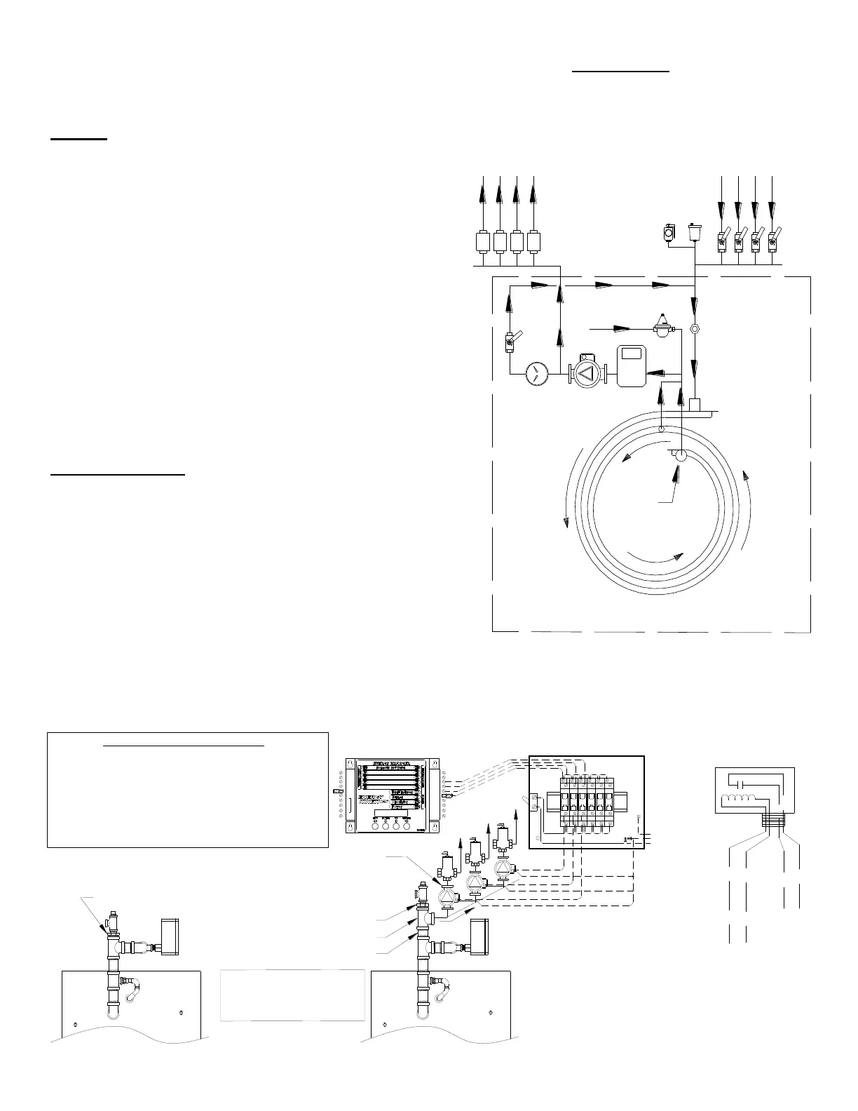
Supply
Return
Return
Supply
Boiler Feed
Energy Converter
Typical Flow
Schematic
Factory piping shown within dashed line
Supply
Boiler Bypass
Digital
Sensor
BOILER PITCH: The Frontier pressure vessel is manufactured with the rear ½ to 1 bubble higher to allow for proper air
removal. This pitch is carefully set at the factory when the boiler is built. Be sure to level the stand prior to mounting the
boiler on the stand. When the stand is level, the pitch is correct and the back of the boiler will be higher than the front.
The EK1 Frontier is pitched 1/4" and the EK2 Frontier is pitched 7/16".
PIPING
All piping and accessory connections should follow good
practice using approved joint sealants.
Figure 2C indicates a typical flow schematic for boiler water
feeding multiple zones. Each system will vary according to
job location.
Supply and return connections are 1”NPT on the EK1 and 1-
1/4”NPT on the EK2.
Call Energy Kinetics to obtain piping and wiring instructions
for alternate applications, such as hydronic heating, radiant
heating, domestic hot water, swimming pool heating, multiple
boilers, injection loops, etc.
Figures 2A and 2B indicate general system piping
arrangement and options. Piping of individual systems may
vary from Figures.
ZONE CONTROL
ZONE CONTROL BY VALVE: The SYSTEM 2000 Boiler is
designed to provide multi-zone control of the heating system and
optionally can supply domestic hot water. Energy Kinetics
recommends and supplies two wire, full port, 24-volt zone valves for
control of each heating zone. A system with a single heating zone
still requires a zone valve to provide control for preheat of unit and
to maintain minimum temperature during operation.
ZONE CONTROL BY CIRCULATOR: Zone control by circulators
requires a flow valve, circulator and 24-volt relay (Multi relay kits or
Individual relays such as a RIB relay available from Energy Kinetics)
for each zone. The main circulator and boiler bypass line are still used in these cases. NOTICE: An additional tee must
be installed into the supply on the inlet side of the main circulator. This tee is the supply for circulators with returns for
these zones into normal return location. Call Energy Kinetics and request “Zoning with Circulators” diagram.
ORANGE
YELLOW
WHITE / YELLOW
WHITE/BLUE
EK# 10-0412-RIB (RIB# 2421C)
24V/120VAC Relay SPDT
24VAC
Coil Leads
To Manager,
Zx & 24V
N/O Contact
Leads
To CIRC,
Power To L1
Full Size Tee (added)
Nipple (added)
Bushing (moved)
1. Remove bushing installed at
factory from boiler supply.
2. Install a nipple (not supplied)
into the existing tee.
3. Install a tee (not supplies) on
to the new nipple.
4. Reinstall the bushing into the
new tee.
SUPPLY
Ground
Neutral
Line
120 VAC
Frontier Boiler Supply Piping
Modified piping for Zone
Circulators.
Looking from rear of boiler.
Circulators w/IFC or Circulators and Flow Checks
(Supply Side Preferred*)
*Circulator may be Installed Return Side
System Manager
5 Zone Circulator Relay Kit
P/N: 10-0412R-5 Shown
ZONE CIRCULATOR RELAY KITS
TO ACTIVATE EACH CIRCULATOR, USING The
SYSTEM MANAGER'S 24VAC OUTPUTS, USE ONE OF
ENERGY KINETICS MULTIPLE ZONE RELAY KITS.
5 ZONE RELAY KIT P/N: 10-0412R-5
10 ZONE RELAY KIT P/N: 10-0412R-10
15 ZONE RELAY KIT P/N: 10-0412R-15
OR INDIVIDUAL 24V RELAY(S) (EK#10-0412-RIB RIB
RELAY OR EQUIVALENT)
Bushing (Installed at Factory)
TEMP. SENS.
R
S
B
A2
A1
B2
CIRC
B1
24VAC
IND
T3
T1
T2
THW
T4
Z1
Z2
Z3
Z4
ZHW

 Loading...