Frontier Oil Heat – PN 10-2021 – October 2021 - 15 -
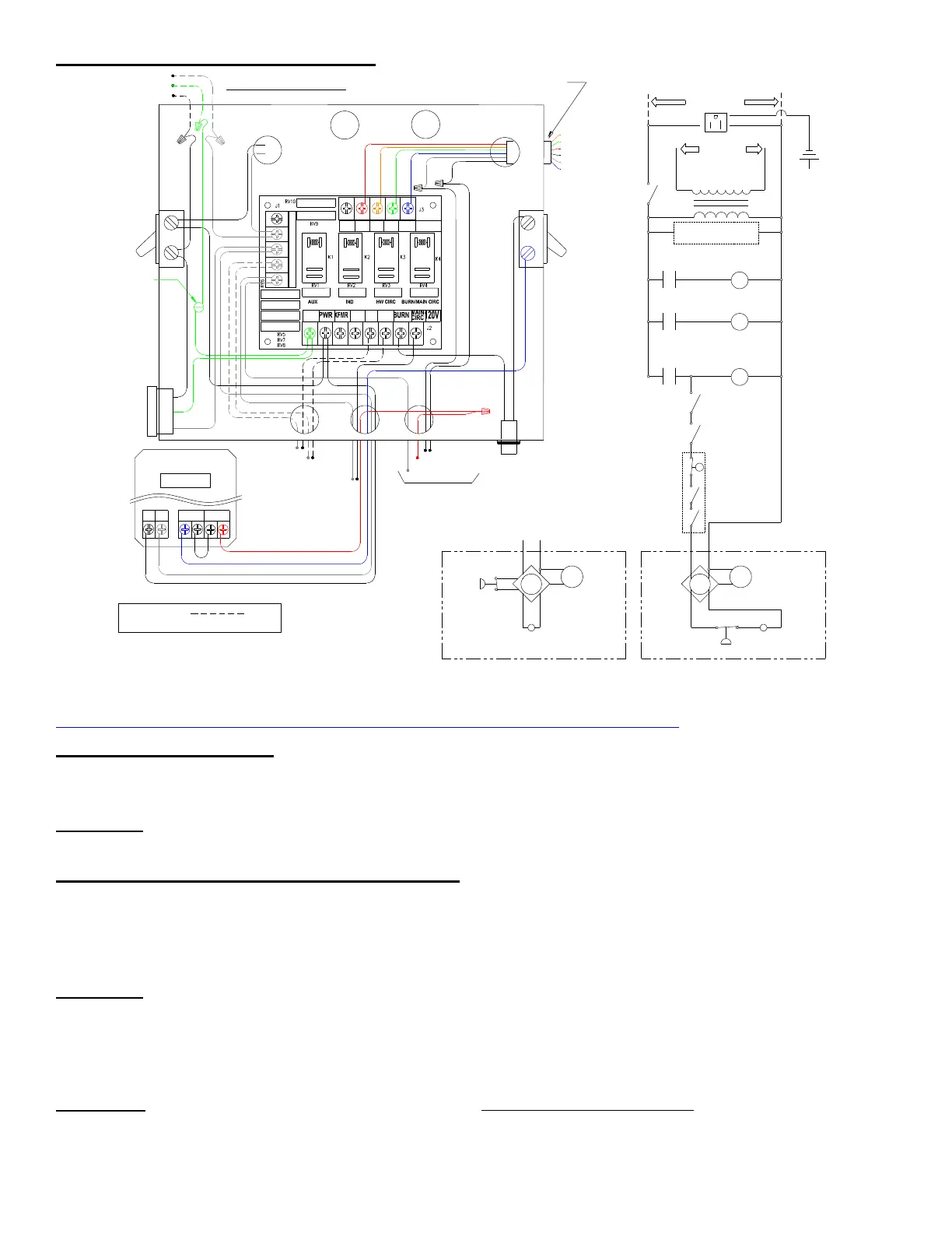
LINE VOLTAGE WIRING DIAGRAMS
See website for alternative replacement of DualGard control with Hydrolevel 3250
http://energykinetics.com/wp-content/uploads/2016/11/dualgard_hydrostat_substitution.pdf
WIRING and CONTROLS
The Frontier Heating System is furnished with controls and basic accessories as illustrated and described in this
manual. Control, burner and accessory instruction sheets and system wiring diagrams should be attached to this manual
for future reference.
DANGER: All wiring for installations in the United States must comply with the NEC, and any local codes. All wiring for
installations in Canada must be done in accordance with the Canadian Electrical Code, Part I.
ELECTRICAL CONNECTION - LINE VOLTAGE
POWER SUPPLY: 120 VOLT 60 HZ, 7.5 Amperes
System 2000 requires 120 VAC. The supply voltage must be within 108 VAC min / 132 VAC max for reliable operation
of the boiler and the Manager. An easy way to check the supply voltage is to plug a voltmeter in at the service outlet
located on the side of the system junction box.
DANGER: Make All Connections with Power Off at Main Circuit Box
Figure 3A: Connect power from a separate 15 AMP fused circuit. Install 3
rd
wire grounding for proper bond between all
electrical accessories. The system switch is included so power can be shut off at the unit for servicing.
Pigtails are provided for the line voltage power connection. Connect black pigtail to hot, white pigtail to neutral, and the
green pigtail to ground.
WARNING: The junction box is wired at the factory with the service outlet always powered, even with the System
Emergency Switch turned off. To have the service outlet controlled by the System Emergency Switch, move the service
outlet black lead to top lug of system switch. A low water cut-off is included on all new systems, but may be field installed
if required by local codes and is available from Energy Kinetics if not included.
USE COPPER CONDUCTORS ONLY
FIELD WIRING
F
F
System
Emergency
Switch
Transformer
50 VA
NO. Relay
Ind/Aux
Inducer
Domestic
HW Circ
NO. Relay
HW Circ
NO. Relay
Burner &
Main Circ
Main Circ
Burner Service
Puff
Switch
Cad Cell
Eye
(Neutral)
White
Black
(Hot)
Line
Voltage
A1
24 V
A2
Switch
Burner Door
Switch
M
Burner
Motor
L1 DualGard L2
Dual Limit Aquastat and
Low Water Cut-Off
(Integrated in DualGard)
Green
(GND)
Beckett Genisys Burner Relay
(Puff Switch wired in series with Cad Cell Eye)
F
F
Cad Cell
Eye
M
Burner
Motor
Carlin 70200 Burner Relay
(Puff Switch wired to BV terminals)
BV
BV
Puff
Switch
TRANSFORMER
POWER LEADS
WHITE
WHITE
BLACK
WHITE
OUTLET
GREEN
GREEN
SWITCH
SYSTEM
#14 WHITE
#14 GREEN
WHITE
BLACK
#14 BLACK
HOT
NEUTRAL
GROUND
BLACK
RED
BLACK
POWER (HOT)
TT
TO BURNER
NEUTRAL
DOOR SWITCH
BLACK
BLUE
BURNER
SWITCH
WHITE
RED
ORANGE
BLACK
GREEN
BLUE
-24 V
-B2
-B1
-IND
-ZHW
-CIRC
(GREEN)
(BLUE)
(WHITE)
(BLACK)
(RED)
(ORANGE)
120 VAC POWER IN
BLACK
BLACK
OUTPUT CABLE FROM
DIGITAL MANAGER
RIGHT SIDE
MAIN CIRC
DOMESTIC HOT
WATER CIRC
INDUCER FAN
GROUND
SCREW
L1 L2
LWCO
LIMIT
WHITE
RED
BLACK
BLUE
WHITE
BLACK
DUALGARD CONTROL
LWCO/LIMIT
RED
BLUE
AUX
IND
HW
24
VAC
CIRC
24V
AUX IND
HW
CIRC
GND
1
2
0
V
N
E
U
T
R
A
L

 Loading...