EasyManua.ls Logo

Enerpac ZU4 Series User Manual

Enerpac ZU4 Series
193 pages
To Next Page IconTo Next Page
Page #1 background imageLoading...
Page #1 background image
Repair Parts Sheets for this product are available from the Enerpac
web site at www.enerpac.com, or from your nearest Authorized
Enerpac Service Center or Enerpac Sales office.
1.0 IMPORTANT RECEIVING INSTRUCTIONS
Visually inspect all components for shipping damage. Shipping
damage is not covered by warranty. If shipping damage is found,
notify carrier at once. The carrier is responsible for all repair and
replacement costs resulting from damage in shipment.
SAFETY FIRST
2.0 SAFETY ISSUES
Read all instructions, warnings and cautions carefully.
Follow all safety precautions to avoid personal injury or
property damage during system operation. Enerpac
cannot be responsible for damage or injury resulting
from unsafe product use, lack of maintenance or incorrect product
and/or system operation. Contact Enerpac when in doubt as to the
safety precautions and operations. If you have never been trained on
high-pressure hydraulic safety, consult your distribution or service
center for a free Enerpac Hydraulic safety course.
Failure to comply with the following cautions and warnings could
cause equipment damage and personal injury.
A CAUTION is used to indicate correct operating or maintenance
procedures and practices to prevent damage to, or destruction of
equipment or other property.
A WARNING indicates a potential danger that requires correct
procedures or practices to avoid personal injury.
A DANGER is only used when your action or lack of action may
cause serious injury or even death.
WARNING: Wear proper personal protective gear when
operating hydraulic equipment.
WARNING: Stay clear of loads supported by hydraulics.
A cylinder, when used as a load lifting device, should never
be used as a load holding device. After the load has been
raised or lowered, it must always be blocked mechanically.
WARNING: USE ONLY RIGID PIECES TO HOLD LOADS.
Carefully select steel or wood blocks that are capable of
supporting the load. Never use a hydraulic cylinder as a shim
or spacer in any lifting or pressing application.
DANGER: To avoid personal injury keep hands and
feet away from cylinder and workpiece during
operation.
WARNING: Do not exceed equipment ratings. Never
attempt to lift a load weighing more than the capacity of the
cylinder. Overloading causes equipment failure and
possible personal injury. The cylinders are designed for a max.
pressure of 10,000 psi (700 bar). Do not connect a jack or cylinder
to a pump with a higher pressure rating.
Never set the relief valve to a higher pressure than the
maximum rated pressure of the pump. Higher settings may
result in equipment damage and/or personal injury.
WARNING: The system operating pressure must not
exceed the pressure rating of the lowest rated component
in the system. Install pressure gauges in the system to
monitor operating pressure. It is your window to what is happening
in the system.
CAUTION: Avoid damaging hydraulic hose. Avoid sharp
bends and kinks when routing hydraulic hoses. Using a
bent or kinked hose will cause severe back-pressure. Sharp
bends and kinks will internally damage the hose leading to
premature hose failure.
Do not drop heavy objects on hose. A sharp impact may
cause internal damage to hose wire strands. Applying
pressure to a damaged hose may cause it to rupture.
IMPORTANT: Do not lift hydraulic equipment by the hoses
or swivel couplers. Use the carrying handle or other means
of safe transport.
CAUTION: Keep hydraulic equipment away from
flames and heat. Excessive heat will soften packings
and seals, resulting in fluid leaks. Heat also weakens
hose materials and packings. For optimum performance do not
expose equipment to temperatures of 150 °F (65 °C) or higher.
Protect hoses and cylinders from weld spatter.
DANGER: Do not handle pressurized hoses. Escaping
oil under pressure can penetrate the skin, causing serious
injury. If oil is injected under the skin, see a doctor
immediately.
Instruction Sheet
ZU4 Series
L2606 Rev. B 08/06
Index:
English:......................1-17
Français:................. 18-35
Deutsch: ..................36-53
Italiano:................... 54-71
Español:.................. 72-89
Nederlands:.......... 90-107
Portuguese..........108-124
Suomalainen........125-141
Norsk...................142-158
Svensk ................159-175
..................176-192
Question and Answer IconNeed help?

Do you have a question about the Enerpac ZU4 Series and is the answer not in the manual?

Enerpac ZU4 Series Specifications

General IconGeneral
SeriesZU4
Maximum Operating Pressure (bar)700
Power SourceElectric
Maximum Pressure (psi)10000
Motor Size (kW)0.75

Summary

Receiving Instructions

Safety Precautions and Warnings

Product Specifications

Performance Chart

Provides output flow rate, motor electrical specifications, and sound level.

Flow Charts

Illustrates the relationship between flow rate, current, and pressure.

Installation Procedures

Reservoir Breather Cap Installation

Details the installation of the breather cap for the reservoir.

Pump Mounting

Provides dimensions for mounting the pump to a fixed surface.

Electrical Connections

Details electrical connection requirements and safety precautions.

Fluid Level Check

Instructions for checking and adding hydraulic fluid to the reservoir.

Hydraulic Connections

Guidance on applying Teflon tape and connecting hydraulic hoses.

Operating Procedures

Manual Valve Operation (VM32)

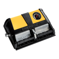
Instructions for operating the VM32 manual valve.

Manual Valve Operation (VM33/VM43)

Instructions for operating the VM33/VM43 manual valve.

Operation with 1 or 2 Button Pendant

How to operate the pump using a 1 or 2 button pendant.

Operation with VE33/VE43 Valves and 3-Button Pendant

Operating pumps with VE33/VE43 valves and a 3-button pendant.

Operation with VE32 Valve and 3-Button Pendant

Operating pumps with VE32 valve and a 3-button pendant.

Operation with VE32D Valve and 1-Button Pendant

Operating pumps with VE32D valve and a 1-button pendant.

Operation with Foot Switch

Instructions for operating valves using a foot switch.

Automatic Operation with Pressure Transducer

How to use automatic pump operation with a pressure transducer.

Automatic Operation with Pressure Switch

How to use automatic pump operation with a pressure switch.

Relief Valve Adjustment

Procedure for adjusting the user-adjustable relief valve.

LCD Interface Instructions

LCD Function Overview

Explains the basic layout and components of the LCD screen.

LCD Operational Buttons

Details the function of the four buttons on the control board.

Available LCD Menus

Lists and describes the various menus accessible via the LCD.

Fault Condition Handling

Clearing LCD Faults

Procedure for clearing fault messages from the LCD display.

Warning Indicators

Low Voltage Warnings

Describes the condition and display for low voltage warnings.

LCD Menu Navigation

Normal Operation Display

Shows the standard 'OK' status and pressure reading.

'Set Pres' Menu (Firmware 5.5)

Allows setting the trigger pressure for valve shift or motor shut-off.

'Units' Menu

Allows selection of pressure units (PSI, BAR, MPa).

'Motor' Menu

Displays motor hours and on/off cycle counts.

'Low Volt' Menu

Displays hours operated in low-voltage conditions.

'Advance' Menu

Displays advance solenoid hours and cycle counts.

'Retract' Menu

Displays retract solenoid hours and cycle counts.

'Local' Mode Menu

Enables local operation mode, bypassing pendant controls.

'Language' Menu

Allows changing the display language of the LCD.

'Diagnose' Menu

Helps troubleshoot pendant problems by displaying button signals.

LCD Hidden Menus

'AUTOMODE' Menu (Firmware 5.6+)

Configures automatic pump control based on pressure limits.

'HI PRESS' Menu (Firmware 5.6+)

Sets the high-pressure limit for motor/valve de-energization.

'LO PRESS' Menu (Firmware 5.6+)

Sets the low-pressure limit for motor/valve re-energization.

'Calibration' Menu (Firmware 5.5)

Allows adjusting the LCD pressure value to match a master gauge.

Maintenance Procedures

Check Oil Level

Procedure for checking and maintaining the hydraulic oil level.

Change Oil and Clean Reservoir

Instructions for changing hydraulic oil and cleaning the reservoir.

Changing Filter Element (Optional)

Procedure for replacing the return line filter element.

Motor Brush Replacement

Instructions for replacing worn motor brushes.

Accessory Installation

Pressure Transducer Installation

Details installation of the pressure transducer for LCD electric pumps.

Pressure Switch Installation

Details installation of the pressure switch for LCD electric pumps.

Troubleshooting Guide

Related product manuals