Do you have a question about the enervent LTR-3 Series and is the answer not in the manual?
Highlights critical safety warnings for operation and maintenance of the unit.
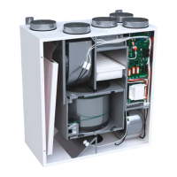
Explains how the LTR-3 unit uses a rotating heat exchanger for heat recovery.
Provides guidance on dimensioning and planning the duct system for optimal airflow.
Outlines the sequential steps for installing the ventilation unit.
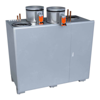
Provides essential instructions for installing duct heaters E09KP-016 and E18KP-016.
Details specific procedures and safety requirements for installing duct heaters.
Explains continuous operation, heat recovery control, and airflow balancing.
Advises on maintaining proper humidity and checking filters for optimal performance.
Electrical connection diagram for the LTR-3 basic model.
Electrical connection diagrams for LTR-3 E09KP and E18KP models.
Lists reasons and actions for the supply air being too cold.
Identifies causes and solutions for decreased air flow.
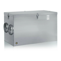
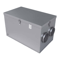
The LTR-3 is a ventilation unit designed for year-round use in small premises and detached houses, featuring regenerative heat recovery. This system utilizes a rotating heat exchanger with aluminum foils to transfer heat from exhaust air to incoming supply air, flowing in opposite directions. This design achieves a high rate of heat recovery, typically ranging from 75% to 85% for supply air heating, depending on the proportion of supply and exhaust air (including heat from the supply air fan). This high efficiency contributes to energy savings and improved indoor air quality, leading to a relatively short payback period.
The LTR-3 range is versatile and adaptable, a result of continuous product development. While basic installation can be performed by users with the help of this manual, installation of units with special functions and extra equipment, as well as general installation work, is recommended to be carried out by qualified electricians and ventilation engineers.
The LTR-3 series includes several models, each with specific fan efficiencies and heating coil configurations:
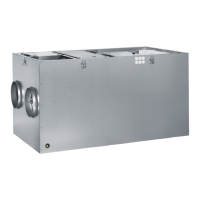
All models feature ducting connections with a diameter of Ø 160 mm.
The ventilation unit is designed for continuous operation, with desired effects regulated from the control panel. Heat recovery can be switched off, for example, during summer when outside and inside temperatures are similar, or to cool indoor air with cool night air. The unit can also recover cool indoor air during summer.
The exhaust air flow should be 5-10% greater than the supply air flow. This is achieved by accurately measuring airflow through all valves using a thermo anemometer and adjusting them to calculated values. A balanced system ensures good heat recovery and maintains a slight negative pressure in the building, which helps keep humidity away from structures. Filters must be clean, and all valves and outer grilles in place during adjustment. No insect net should be placed over the fresh air grille.
This panel controls the fans with four speed positions and includes an HRW (Heat Recovery Wheel) switch with an indicator light.
A heating regulator and duct temperature sensor (0-30°C) are used for external heating control.
Features a capillary thermostat with a supply air temperature switch and an overheating protection reset button.
These heaters include a reset button for overheating protection.
The unit can be installed in warm, half-warm, or cold rooms. For cold room installations, a 100 mm thick isolation cover is required. It should be placed on a plain surface with elastic sound-muffling material (e.g., a 100 mm thick isolation plate). The unit can be mounted on its edge with the front edge higher than the back. For facilities with swimming pools, the unit must be drained using one of the two provided drain outlets. If installed in a cold room, the drain pipe must be insulated to prevent freezing.
A minimum of 60 cm free space is required in front of the service hatch for access and electrical inlets. Silencers are recommended for exhaust and supply air ducts.
Professional engineering is recommended for duct system dimensioning. Ducts should be large enough (min. Ø 100 mm) for low air speed, with outside feed and waste air ducts, and outside grille, being Ø 160 mm. No insect net behind the grille. Only type-approved materials (galvanized spiral-weld or plastic pipe) and mechanical ventilation valves (Ø 100 mm or larger for supply and exhaust) should be used.
Outside air intake should ideally be from the north side or a shady place with minimal temperature variations. Waste air should be led out about 90 cm above the roof saddle, using insulated factory-made fittings and a cover to prevent rainwater entry. Control hatches should be placed for duct cleaning.
Exhaust air valves are typically in toilets, kitchens, washrooms, bathrooms, clothing storage, cleaning cupboards, and utility rooms. Supply air valves are in bedrooms, living rooms, dining recesses, hobby rooms, dressing rooms, and saunas (innermost corner, directed above the stove). Air flows from supply to exhaust areas through door chinks (20 mm, 100 mm for sauna) or "free flow" grilles. Additional supply air can be ducted directly to wood-burning fireplaces (closable duct).
Garages or workshops should not be connected to the house ventilation system; they require independent systems. Cooker extractor hoods should not be connected to the house ventilation system to prevent blockage of the heat exchanger by steam and grease. A fan-assisted drying cabinet can be indirectly connected to an exhaust valve, requiring at least 12 l/s airflow. Hard silencers (09 for exhaust, 09 or 06 for supply) are recommended.
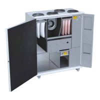
The LTR-3 requires no mechanical maintenance other than periodic filter changes and cleaning of the heat exchanger and fans.
After opening the service hatch, wait two minutes before starting maintenance. Power supply is cut when the hatch is opened, but fans may still rotate, and the electrical coil in E-/EP-models remains hot for a while. The hatch is opened by releasing lock bolts. There are no user-serviceable parts behind the control panel; contact a service technician for repairs. Always clarify the cause of a fault before restarting the unit.
When changing filters, inspect the heat exchanger. If cleaning is needed, remove it and wash through the air channels with a hand shower and neutral detergent. Compressed air can also be used. Do not use a pressure washer or submerge the heat exchanger in water. After cleaning, ensure the rotor turns freely.
Inspect fans when changing filters. If cleaning is needed, remove them and clean with a toothbrush or compressed air.
Filters should be changed every four months maximum. Pull out filter cassettes, loosen fabric from the frame, replace with new fabric, and press cassettes back into place with the support network facing the heat exchanger. Vacuum-cleaning the inside of the device is recommended.
The heat exchanger rotates via a belt. If worn or broken, it can be replaced by:
If the manual reset overheating cut-out activates:
Make a Ø 12 mm hole in the supply air duct 50 cm after the heater (towards the room) and attach the temperature sensor using its base. Cabling is drawn from the sensor to the Pulser regulator according to regulations.
The Pulser regulator is installed on a mounting box according to valid regulations.
Always ventilate with sufficient efficiency to prevent high indoor humidity and condensation on cold surfaces. Recommended relative humidity is 40-45% (at 20-22°C). Monitor humidity; increase ventilation if it rises above 45%, or reduce if it falls below 40%. Change filters regularly, especially the exhaust air filter in winter, as it gets dirty faster, leading to decreased airflow, increased humidity, and lower incoming air temperature. Check heat exchanger function with every filter inspection.