Do you have a question about the ENERVEX BEF 225x and is the answer not in the manual?
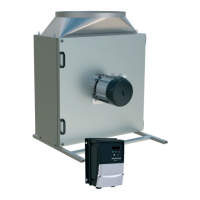
Identifies the ENERVEX BEF 225-800X Box Ventilator model.
Lists primary uses like laundry rooms, dryers, kitchen/bathroom exhaust.
Explains hazard symbols like DANGER and WARNING used in the manual.
Outlines essential safety rules for operating the unit to prevent hazards.
Covers positioning, mounting, and duct connections for the ventilator.
Details wiring, motor controller connection, and grounding requirements.
Instructions for managing the keypad, operating display, and changing parameters.
Procedures for cleaning, servicing, and ordering replacement parts.
Critical warning about connecting the EC motor only to an approved controller.
Provides general guidelines and special requirements for the BEFx fan line.
Highlights efficiency, backward curved impeller, materials, insulation, and motor features.
Lists and illustrates the parts included with the box ventilator.
Specifies acceptable temperature ranges for operation.
Warns against transporting solid particles or use in explosive gas areas.
Details how ventilator units are shipped and handled to prevent damage.
Lists optional accessories like exhaust and pressure controls.
References UL, CSA, and AMCA standards the product complies with.
Warns to install duct fan at least one meter from accessible openings.
Detailed specs including voltage, motor rating, EDrive model, power, and temperature for various models.
Illustrates the physical dimensions (A-H) of the BEFx ventilator.
Shows acceptable ways to orient the ventilator unit.
Emphasizes ensuring 90° access door opening for maintenance.
Warns against operating the ventilator with the access door open.
Instructions for mounting on level, stable surfaces, including support leg installation.
Guidance on hanging the unit from the ceiling using brackets and proper bolt sizing.
Best practices for connecting to duct systems for optimal performance.
How to use flexible ducting to reduce system vibration.
Guidelines for outdoor installations, including roof mounting and gooseneck use.
Attaching gooseneck to outlet collar, avoiding screens.
Proper attachment of the junction box to minimize water ingress and conduit strain.
Critical warning not to install the Field Junction Box on the service door.
Compliance with codes, conduit types, and EC-motor wiring considerations.
Details on the factory-programmed EDrive controller and its mounting distance.
Requirements for installing a disconnect switch and its operation.
Discusses bearing currents and the EDrive's insulated rotor system.
Danger warning regarding the motor speed drive's circuit capacity.
Specifies mounting location accessible only to qualified personnel within 300 ft.
Covers system ground, protective earth conductor, and safety ground requirements.
How to disconnect the EMC filter if needed for specific applications.
Danger warning for qualified electrical personnel only to install and service.
Details on cable core requirements, lengths, and earth connection for motor to EDrive.
Advises against switching devices between drive and motor and interlocks.
Illustrates the typical wiring for BEF 225-355x models with 120V supply.
Danger warning about high voltage capacitors in the EDrive requiring discharge time.
Shows typical wiring for BEF 225-800x models with 208-480V supply.
Critical warning not to connect line voltage directly to the motor.
Instructions on how to verify the correct counterclockwise rotation of the impeller.
Guidance on interlocking safety systems like PDS for fan operation proof.
Warning about the importance of correct wheel rotation for performance and motor health.
Explains the functions of the NAVIGATE, UP, DOWN, RESET/STOP, and START keys.
Describes how the display shows status, frequency, current, and power.
Step-by-step guide to modifying drive parameters using the keypad.
How to view parameters without making changes.
Procedures for resetting parameters to factory defaults or clearing faults.
Explains the behavior and meaning of the EDrive's 7-segment LED display.
Detailed steps for performing the essential Auto Tune sequence for proper operation.
How safety systems prove fan operation, especially if PDS is not integrated.
Recommended inspection and cleaning frequency, especially for dryer applications.
Step-by-step guide for cleaning the impeller and housing.
Notes on available spare parts and motor bearing service.
Danger warning to always disconnect and lock power before servicing.
Warning to make the unit non-functional during cleaning for safety.
Provides an illustrated breakdown of components for ordering.
Advises to have model and part position numbers ready for ordering.
Covers the 2-year functional failure warranty for material and workmanship defects.
Details what is not covered, like labor costs, misuse, or unauthorized alterations.
Information on how to contact ENERVEX Customer Service for warranty claims.
| Model | BEF 225x |
|---|---|
| Category | Fan |
| Phase | 1 |
| Frequency | 50 Hz |
| Motor Voltage | 200-240 V |
| Voltage | 200-240 V |