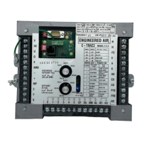
A C-TRAC3
13 of 21 Jan 13 R5
Auxiliary Alarm indicates a failure of an external binary input into one of the optional programmable C-
TRAC3 terminals. Refer to the unit function sheet and wiring diagram to determine what type of input and
which terminal. Typically, this input would be a filter switch or a current sensor.
Low Air Flow is a noted indication of either the VFD operating at too low of a speed, or an open air flow
switch (if used). Refer to the unit function sheet and wiring diagram to determine which type and
terminal.
LOW LIMIT
The C-TRAC3 control will have low limit (freeze) protection included as a standard option. To reset the
control after a low limit trip the C-TRAC3 must have the power removed and restored to terminals H and
N. This is usually done by turning the unit off at the service switch located inside of the control cabinet. A
computer or EMS can also command the C-TRAC3 to reset the air handler from a low limit alarm.
On initial start-up the C-TRAC3 will bypass low limit sensing for a pre-set amount of time, determined by
the size and type of heat exchanger, the ambient temperature and the discharge air sensor temperature.
The bypass timer is also reset if the minimum position is increased by more than 15% or the VFD feedback
signal increases by more than 10%. This is to avoid nuisance low limit tripping while the heat exchanger is
recovering from a sudden increase in air. The anti-nuisance time is set to 30 seconds for all applications,
and will automatically reset itself if the temperature rises above the low limit setpoint.
If the discharge air temperature approaches the low limit setpoint on equipment incorporating an
economizer mixing box function, the C-TRAC3 will automatically decrease the minimum position down to
½ of its original setting.
VARIABLE AIR VOLUME
Variable air volume and 2 speed systems change the amount of air being moved by the system using a
variety of means. The C-TRAC3 can accept the feedback signal of a variable frequency drive, connected to
input terminals on the C-TRAC3 (0-10Vdc). Refer to the wiring diagram to determine which terminals are
used. The C-TRAC3 is capable of adjusting the temperature control according to the change in the air
volume signal. For example, on a significant decrease in airflow, the C-TRAC3 will force unnecessary
compressors off to avoid possible damage to the refrigeration components. Reduced airflow would also
limit the number of cooling stages that could operate. A sudden volume change will also affect the heating
control. The heating ramp responds more quickly to increase the heating output on an increase in air
volume. Additionally, the internal low limit bypass time is reset on a sudden increase in air volume.
On units equipped with mixing dampers, the C-TRAC3 can increase the minimum position during a
decrease in air volume. This is to maintain the minimum required amount of outside air. For example, an
RTU delivering 10,000cfm at 10% minimum outside air should be moving 9000cfm return air and 1000cfm
outside air. If the VFD was reduced to 50% volume we would be delivering 4500cfm return air and 500cfm
outside air = 5000cfm total. The minimum fresh air required is still 1000cfm. To account for this, the
damper minimum position will be increased to allow 1000cfm of outside air and 4000cfm of return air.

 Loading...