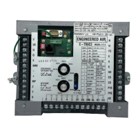
A C-TRAC3
19 of 21 Jan 13 R5
SERVICE NOTES
Dehumidification Mode
Any temperature reset methods used for normal operation are still active to affect the reheat temperature
if the equipment is enabled to dehumidification mode.
Room Sensor/Setpoint
The standard modulating room sensor is a Johnson Controls
®
TE-6100-960 that comes complete with a
setpoint dial. Optionally, the setpoint dial in the room can be disabled in favor of the second setpoint dial
on the face of the C-TRAC3.
Field Installed Discharge Air Sensor
The location of this sensor is critical to the performance of the equipment and is the most likely cause of
poor temperature control. If it is too close to the heat exchanger it may pick up radiant heat and cause the
equipment to discharge an actual temperature much lower than what is being read by the
C-TRAC3. If it is mounted too far downstream there will be too much lag in the response of the change in
temperature, and will cause the actual discharge temperature to hunt up and down. Refer to the
equipment Installation Operation and Maintenance manual for mounting location details.
DJM2 Setup Notes
Set the DJM2 heating controller to be a fully proportional control by adjusting the CONT potentiometer to
the full counter clockwise position. Adjust the BMSS pot so that the burner comes on at 3.0Vdc and the
BMSZ pot so that the burner shuts off at 2.5Vdc. The precision of the BMSS and BMSZ pots is not overly
critical as the
C-TRAC3 will learn at what input the burner comes on and off, and will adjust its internal temperature
algorithms to compensate for any error.
G-TRAC2 Setup Notes
Add a 1k ohm resistor between G-TRAC2 terminals Q and U. Set block ‘C’ DIP switch 5 to disable the low
limit, and set 3 and 4 to the closed position. Block ‘A’ DIP switches 1, 2, 3, 4 and 5 must be off. With the
C-TRAC3 calling for maximum heat (10 Vdc into G-TRAC2 terminals + and -), adjust the BMS reset pot so
that the burner reaches full fire at 9.25Vdc (G-TRAC2 terminals PL and PG). The gas valve actuator will be
near fully open.
Two Speed Motors
Generally two speed motors do not present a problem to the stability of C-TRAC3 controller. It may,
however, be configured to operate similar to a VFD, using load shedding and minimum position
compensation. In this case, when the motor is turned to high speed, a contact between terminals V and
MP will close to notify the C-TRAC3 of high speed.
Tandem Compressors
If all the compressors are connected to the C-TRAC3 output contacts, there are no programming changes
required. However if the second compressor of the tandem set is operated from a pressure switch the
C-TRAC3 inter-stage time is increased to 8 minutes minimum.

 Loading...