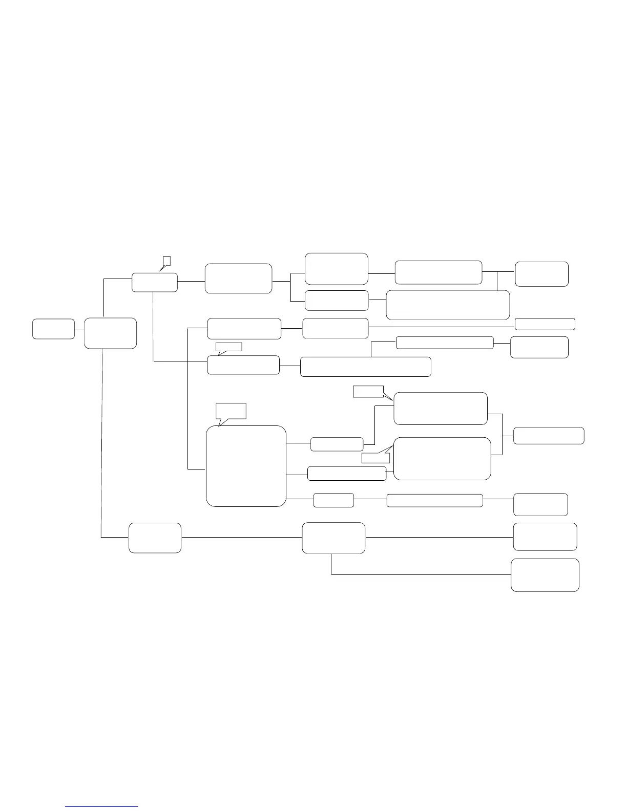
Interval moving
Input voltage DC12V, 0~10A The compressor is Replace the
Compressor Yes DC12V, 4.2A DC24V, 0~5A locked, or contaminated cooling unit
works DC24V, 2.1A
No Lower than rated Gas is leaking or no compression
No amperage ( surface of condenser is
ambient temperature
No cooling DC cord Wiring and couplers No good Change couplers
fuse blow are connected
out (12V) Thermister is broken (∞Ω) Replace the
thermister
Yes Resistance of Disconnect the coupler and check
the thermister 2-10kΩ ( good ), ∞Ω ( bad )
Compressor coil is
open circuit.
In case open-circuit: ∞Ω
Input voltage and Replace cooling unit
resistance at the AC 14~18V Compressor is locked, or
terminal of coil short-circuit
compressor. In case locked: 1.23Ω ※1
AC 14〜18V (normal) Lower than approx. 14V In case short-circuit: 0Ω
1.23Ω( normal ) ※1
Input voltage,12〜30V
Ambient temp. 25℃ AC 0V Power Supply is broken Replace
Power Supply
Check +, - Input connection: No Go to A
at input cord +, - is reversed. Check the fridge
from battery.
Yes Check the vehicle.
Bat. Voltage, wiring,
fuse, etc.
※1 This data come from Laboratory standard measurement.
6-1
6-2
 Loading...