6. CHECKING POINTS & MEASURING
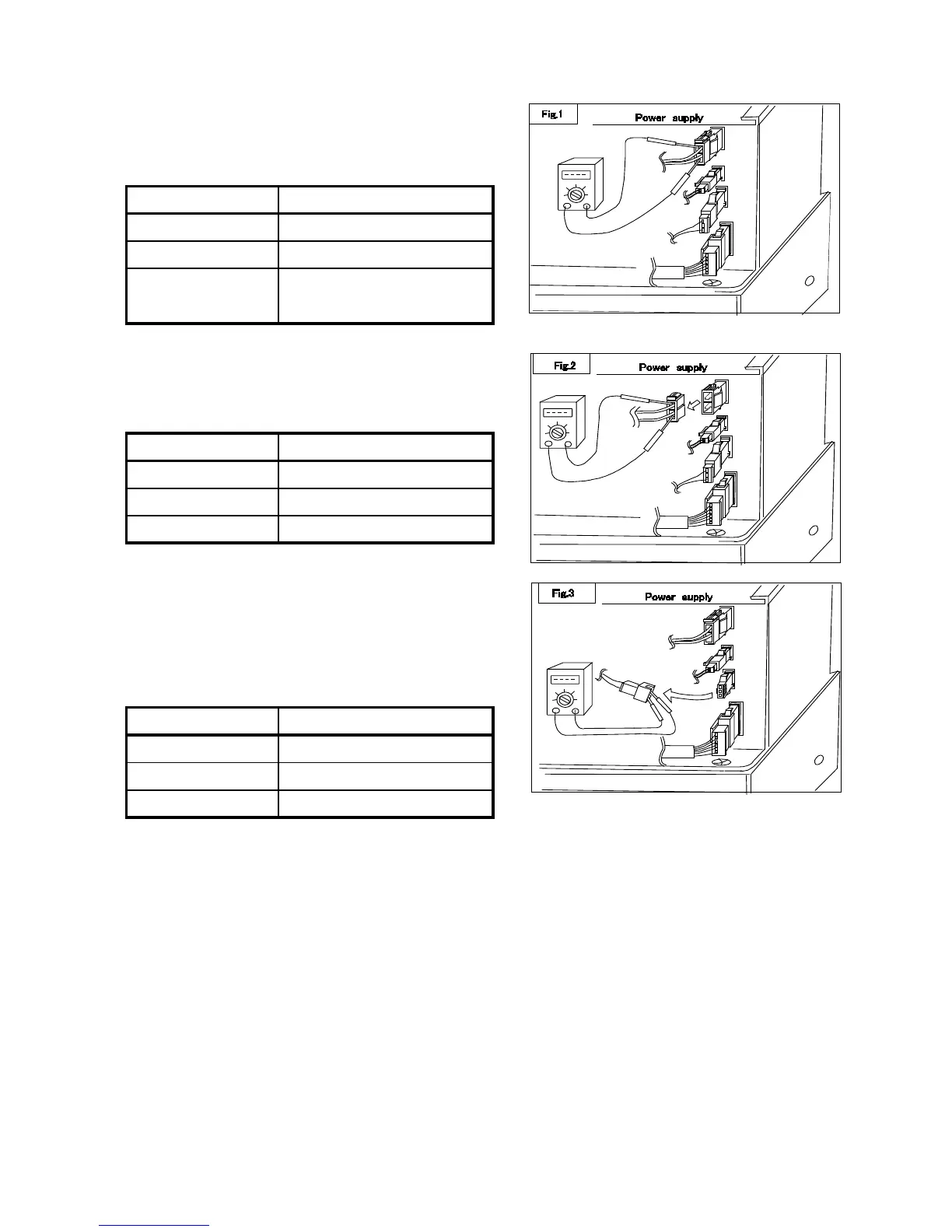
6-1 Compressor input voltage (Fig. 1)
・Measure at 2 poles coupler of Power Supply
or at the input terminals of the compressor.
(Keep to connect the compressor when you measure it.)
Readings Judgment
Approx. AC14〜18V
Normal
AC 0 V Power Supply is broken
6-2 Compressor coil resistance (Fig.2)
Unfasten 2 poles coupler to the compressor and measure.
Readings Judgment
Approx. 1.23 Ω ※1 Normal
∞Ω Broken (open circuit)
0Ω Broken (short circuit)
※1 This data come from Laboratory standard measurement.
6-3 Thermistor resistance (Fig.3)
Unfasten the 3 poles coupler at the Power Supply and meature
Readings Judgment
Approx. 2 kΩ〜10 kΩ
Normal
∞Ω Broken (open circuit)
0Ω Broken (short circuit)
Note ) Compressor runs continuously when you make to short circuit at this coupler.
6
Approx. AC14V or lower
and interval moving
Compressor is locked
 Loading...