Do you have a question about the enphase IQ8MC and is the answer not in the manual?
Explains safety symbols indicating hazards like danger, warning, and note.
Provides general safety guidelines for installation and operation.
Details UL-listed PV rapid shutdown equipment and NEC/CSA requirements.
Specifies requirements for initiating devices and permanent labeling for rapid shutdown.
Details IQ Gateway's role in monitoring, propagation, and communication.
Explains MPPT for maximizing individual PV module energy production.
Details electrical and mechanical compatibility requirements for PV modules.
Lists necessary Enphase components like IQ Gateway, IQ Cable, etc.
Details on mounting microinverters under PV modules, considering clearance.
Instructions for connecting PV module DC leads to microinverters and checking LEDs.
Steps to safely energize the system and check microinverter status LEDs.
Explains meanings of LED colors: flashing green, orange, red, solid red.
Explains LED colors and their meanings for microinverter status.
Describes the solid red LED status and its causes and resolution.
Steps to clear the "DC Resistance Low - Power Off" error via the Installer Platform.
Emphasizes de-energizing circuits and avoiding disconnects under load.
Steps for safely disconnecting a microinverter from the IQ Cable and PV module.
Emphasizes matching PV module voltage/current to microinverter specifications.
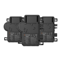
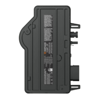
Detailed technical specifications for the IQ8MC-72-M-US microinverter model.
Detailed technical specifications for the IQ8AC-72-M-US microinverter model.
Detailed technical specifications for the IQ8HC-72-M-US microinverter model.
| Model | IQ8MC |
|---|---|
| Manufacturer | Enphase |
| Category | Microinverter |
| Nominal Output Voltage | 240 V |
| Nominal Frequency | 60 Hz |
| Max DC Input Voltage | 60 V |
| Enclosure Rating | IP67 |
| Maximum Input Power | 440 W |
| Start-up Voltage | 22 V |
| Maximum Output Power | 330 VA |
| Warranty | 25 years |
| Efficiency | 97.0% |
| Operating Temperature Range | -40°C to +60°C |