Enphase IQ8P Microinverters
16 © 2024 Enphase Energy Inc. All rights reserved. January 2024
IOM-00002-1.0
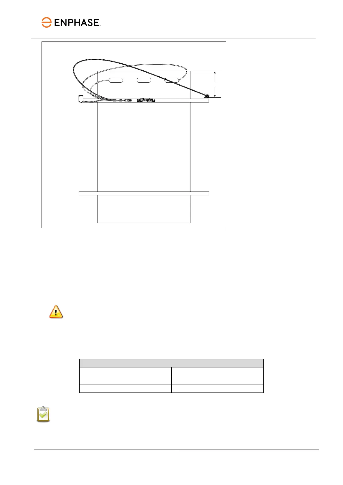
Step 1: Position the IQ Cable
A. Plan each cable segment to allow drop connectors on the IQ Cable to align with each PV
module. Allow extra length for slack, cable turns, and any obstructions.
B. Mark the approximate centers of each PV module on the PV racking.
C. Lay out the cabling along the installed racking for the AC branch circuit.
D. Cut each segment of cable to meet your planned needs.
WARNING: When transitioning between rows, secure the cable to the rail to prevent
cable damage or connector damage. Do not count on the connector to withstand
tension.
Step 2: Position the junction box
A. Verify that the AC voltage at the site is within range.
Service type and voltage: L1-L2
240 VAC split-p
211 to 264 VAC
220 VAC single-p
198 to 242 VAC
220 VAC three-p
198 to 242 VAC
NOTE: All installations require that you use the Enphase IQ Gateway to commission the
microinverters to propagate correct grid profile settings. This will also ensure that the
microinverter’s firmware is upgraded whenever a newer version is available.
B. Install a junction box at a suitable location on the racking.